14. INVERTER CONNECTION
14.5 FREQROL Series Inverter Side Settings
14 - 29
INVERTER CONNECTION
14
14.5.6 Connecting FREQROL-E700 series
Communication settings
Make the communication settings of the inverter.
Be sure to perform the inverter reset after updating each parameter.
(1) Communication port and corresponding parameters
(2) Communication settings of inverter
Set the following parameters using the PU (parameter unit).
Do not change these parameters, even though they can be monitored from the GOT. If they are changed,
communication with the GOT is disabled.
*1 Setting items are parameter names described in the manual of FREQROL-E700 series.
*2 Settings on the GOT can be changed.
When changing the settings on the GOT, be sure to change the parameters on the inverter to correspond with the GOT settings.
*3 Inverter default values (No need to change)
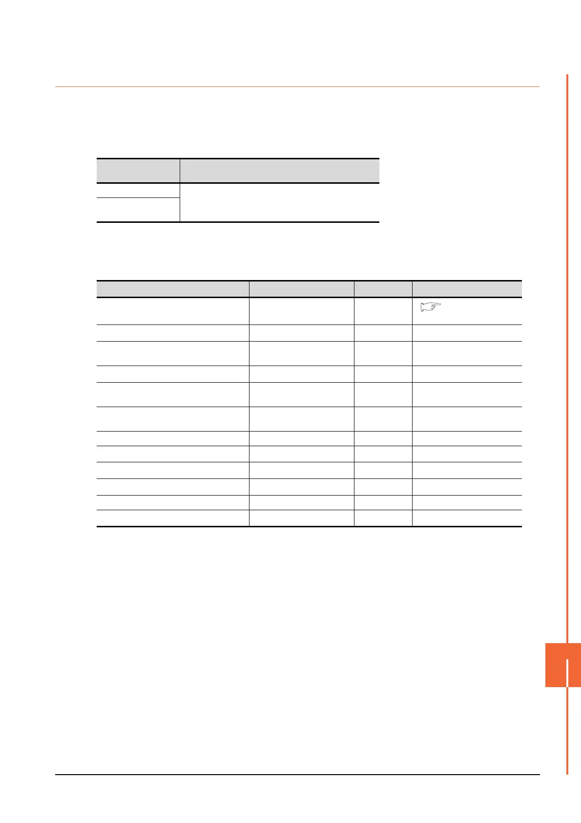
GOT connection
destination
Parameters corresponding to inverter
PU connector
Pr.79, Pr.117 to Pr.124, Pr.340, Pr.342, Pr.549
FR-E7TR
(RS-485 terminal block)
Setting item
*1
Parameter No. Set value Contents of setting
PU communication station number Pr.117 0 to 31
14.5.14 Station number
setting
PU communication speed
*2
Pr.118
192
*3
19200bps
PU communication stop bit length
*2
Pr.119 10
Data length: 7bit
Stop bit length: 1bit
PU communication parity check
*2
Pr.120 1 Odd
Number of PU communication retries Pr.121 9999
The inverter will not come to an
alarm stop.
PU communication check time interval Pr.122 9999
Communication check
suspension
PU communication wait time setting Pr.123 0 0ms
PU communication CR/LF selection Pr.124
1
*3
With CR, without LF
Protocol selection Pr.549
0
*3
Mitsubishi inverter protocol
Operation mode selection Pr.79
0
*3
PU operation mode
Communication startup mode selection Pr.340 1 Network operation mode.
Communication EEPROM write selection Pr.342
0
*3
Written to RAM and EEPROM

 Loading...


