14. INVERTER CONNECTION
14.3 Connection Diagram
14 - 17
INVERTER CONNECTION
14
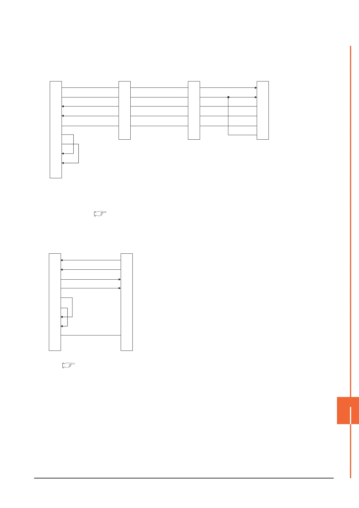
*1 Connect a terminating resistor jumper to RDB and RDR which are assigned in the FR-A5NR of the inverter located farthest from
the GOT.
The terminating resister jumper is packed together with the FR-A5NR.
*2 Set the terminating resistor of GOT side, which will be a terminal, to "Enable".
1.4.3 Terminating resistors of GOT
*1 Set the terminating resistor to "Disable".
1.4.3 Terminating resistors of GOT
*2 RDA2, RDB2, SDA2 and SDB2 terminals of the RS485
terminal block (built into the inverter) cannot be used.
(4) RS485 connection diagram 4)
RDA
RDB
SDA
SDB
SG
RDR
1
6
2
7
5
3
8
4
9
-
FR-A5NR side
(terminal block)
Station No.0
RDA
RDB
SDA
SDB
SG
RDR
FR-A5NR side
(terminal block)
Station No.1
RDA
RDB
SDA
SDB
SG
RDR
FR-A5NR side
(terminal block)
Station No.n
GOT side
*
2
*
1
SDA
SDB
RDA
RDB
SG
RSA
RSB
CSA
CSB
FG
(5) RS485 connection diagram 5)
GOT side
*
1
RDA
RDB
SDA
SDB
RSA
RSB
CSA
CSB
SG
FG
2
7
1
6
3
8
4
9
5
-
SDA1(TXD1+)
SDB1(TXD1-)
RDA1(RXD1+)
RDB1(RXD1-)
SG(GND)
Inverter side
RS485 terminal block
(built into the inverter)
*
2

 Loading...


