5 - 32
5. ETHERNET CONNECTION
5.4 PLC Side Setting
[Controller Setting] and [Ethernet] of GT Designer3
For [Controller Setting] and [Ethernet] of GT
Designer3, refer to the following.
5.3.1 Setting communication interface
(Communication settings)
5.4.6 Connecting to Ethernet
module (A Series)
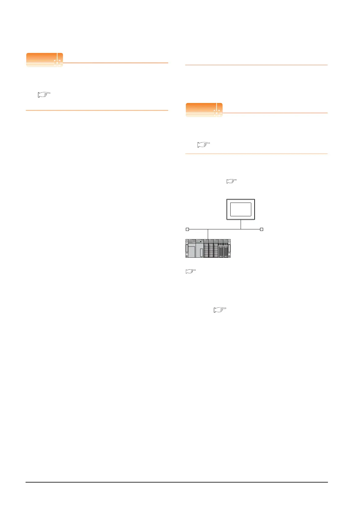
This section describes the settings of the GOT and
Ethernet module (A Series) in the following case of the
system configuration.
Ethernet module (A Series)
For details of the Ethernet module (A Series), refer to
the following manual.
For A Ethernet Interface Module User’s Manual
System configuration
*1 The Ethernet module is mounted on the base unit slot 0.
The Start I/O No. of the Ethernet module is set to "0".
*2 These setting items do not exist at the PLC side. However,
the virtual values must be set on the GOT side.
■ [Controller Setting] and [Ethernet] of GT Designer3
<GOT> (The settings other than the
following are set to the default)
*2
*2
*1
Network No.
: 1
PLC No. : 1
IP address : 192.168.0.18
Port No. : 5001
Communication format : UDP (fixed)
Network No. : 1 (virtual)
PLC No. : 2 (virtual)
IP address : 192.168.0.19
Port No. : 5001
Communication format : UDP(fixed)
<Ethernet module> (The settings other than the
following are set to the default)
[Controller Setting] and [Ethernet] of GT
Designer3
■
■ Switch settings of Ethernet module
■ Sequence program

 Loading...


