5 - 28
5. ETHERNET CONNECTION
5.4 PLC Side Setting
(1) Controller setting
(2) GOT Ethernet setting
(3) Ethernet setting
*1 Set the same value as that of GOT N/W No.
*2 Set a value different from that of the GOT PLC No. and the
PLC No. of other PLCs on the same network.
Checking communication state of C
Controller module
(1) When using the Command Prompt of Windows
.
Execute a Ping command at the Command Prompt of
Windows
.
(a) When normal communication
C:\>Ping 192.168.3.1
Reply from 192.168.0.1: bytes=32 time
<10ms TTL=32
(b) When abnormal communication
C:\>Ping 192.168.3.1
Request timed out.
(2) When abnormal communication
At abnormal communication, check the followings and
execute the Ping command again.
• Cable connecting condition
• Confirmation of switch and network parameter setting
• Operation state of PLC CPU (faulty or not)
• The IP address of C Controller module specified in the
ping command
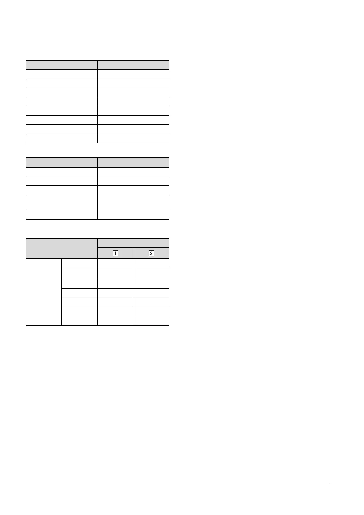
Item Set value (Use default value)
GOT Net No. 1
GOT Station 1
GOT Ethernet Setting 192.168.3.18
GOT Communication Port No. 5001
Retry 3times
Startup Time 3sec
Timeout Time 3sec
Delay Time 0ms
Item Set value (Use default value)
GOT IP Address 192.168.3.18
Subnet Mask 255.255.255.0
Default Gateway 0.0.0.0
Peripheral Communication Port
No.
5015
Transparent Port No. 5014
Item
Set value
Ethernet setting
No.1
Host * -
N/W No.
1
*1
1
*1
PLC No.
2
*2
3
*2
Type QnD(H)CCPU QnD(H)CCPU
IP address 192.168.3.1 192.168.3.2
Port No. 5006 (fixed) 5006 (fixed)
Communication UDP (fixed) UDP (fixed)

 Loading...


