8 - 24
8. BUS CONNECTION
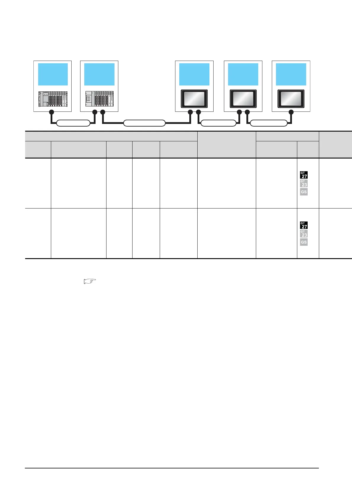
8.2 System Configuration
When 2 to 3 GOTs are connected
*2
*1 The connection of multiple GOTs
When connecting to multiple GOTs with GT 16, GT15 and GT11 mixed, use GT11 as a terminal.
*2 The number of connectable GOTs is restricted according to the CPU type and the number of intelligent function modules.
8.4.12 When connecting multiple GOTs
Extension base
unit
1st GOT
Main base unit
Connection cable 2)
Extension cable
2nd GOT 3rd GOT
Connection cable 3)
Connection cable 4)
PLC
*2
Connection cable 2)
GOT (1st)
*1
Extension
base
Extension cable Main base
Connection
cable 1)
Bus connector
conversion box
Option device
*4*5
Model
- - Main base - -
GT15-A370C12B-S1(1.2m)
GT15-A370C25B-S1(2.5m)
GT15-75ABUS2L
GT15-ABUS2
Extension
base
GT15-A370C12B(1.2m)
GT15-A370C25B(2.5m)
Main base - -
GT15-C12NB(1.2m)
GT15-C30NB(3m)
GT15-C50NB(5m)
GT15-75ABUS2L
GT15-ABUS2

 Loading...


