8. BUS CONNECTION
8.2 System Configuration
8 - 27
8
BUS CONNECTION
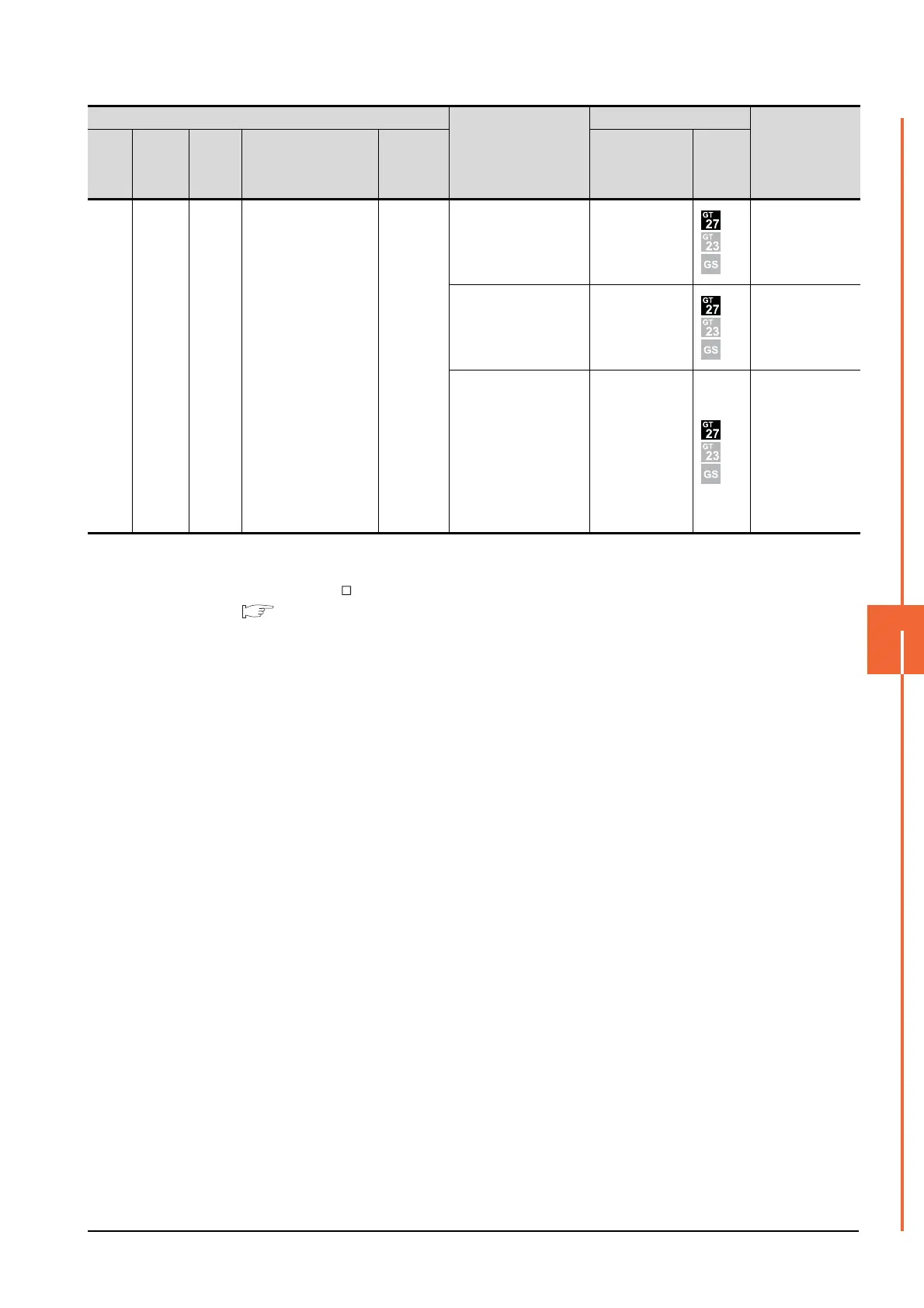
*1 For details on the extension cables, refer to the MELSEC-A/QnA catalog (L(NA)8024).
*2 Use the A168B for the extension base unit.
*3 When installing the GOT 30m or more away from the main base unit, the bus connector conversion box is required.
*4 When using GT15-C EXSS-1, connect as the following precautions.
8.4.1 GT15-C [ ] EXSS-1, GT15-C [ ] BS
*5 When using the following functions, use GT15-QBUS(2). GT15-75QBUS(2)L cannot be used.
Remote personal computer operation (Serial), video display function, multimedia function, external I/O device, RGB display
function, sound output function
Main
base
Extension
cable
Extensi
on
base
-
-
GT15-A1SC05NB(0.45m)
GT15-A1SC07NB(0.7m)
GT15-A1SC30NB(3m)
-
-
A7GT
-CNB
*3
GT15-A1SC07B(0.7m)
GT15-A1SC12B(1.2m)
GT15-A1SC30B(3m)
GT15-75ABUSL
GT15-75ABUS2L
GT15-ABUS
GT15-ABUS2
Between extension
base and GOT: 3m
(Including the
extension cable
length)
GT15-C100EXSS-1(10m)
GT15-C200EXSS-1(20m)
GT15-C300EXSS-1(30m)
*4
GT15-75ABUSL
GT15-75ABUS2L
GT15-ABUS
GT15-ABUS2
Between extension
base and GOT: 33m
(Including the
extension cable
length)
GT15-C100EXSS-1(10m)
GT15-C200EXSS-1(20m)
GT15-C300EXSS-1(30m)
*4
GT15-75ABUSL
GT15-75ABUS2L
GT15-ABUS
GT15-ABUS2
Between extension
base and GOT: 33m
Between extension
base and bus
connector
conversion box: 3m
(Including the
extension cable
length)
PLC
Connection cable 2)
GOT1000 Series
Max. distance
Main
base
Extension
cable
*1
Extensi
on
base
*2
Connection cable 1)
Bus
connector
conversion
box
Option device
*5
Model

 Loading...


