EasyManuals Logo

Mitsubishi GOT2000 Series Connection Manual

Mitsubishi GOT2000 Series
674 pages
To Next Page IconTo Next Page
To Previous Page IconTo Previous Page
Page #323 background imageLoading...
Page #323 background image
9. MELSECNET/H CONNECTION (PLC TO PLC NETWORK), MELSECNET/10 CONNECTION (PLC TO
PLC NETWORK)
9 - 35
MELSECNET/H CONNECTION (PLC TO PLC NETWORK),
MELSECNET/10 CONNECTION (PLC TO PLC NETWORK)
9
Connection to Q170MCPU or Q170MSCPU(-
S1)
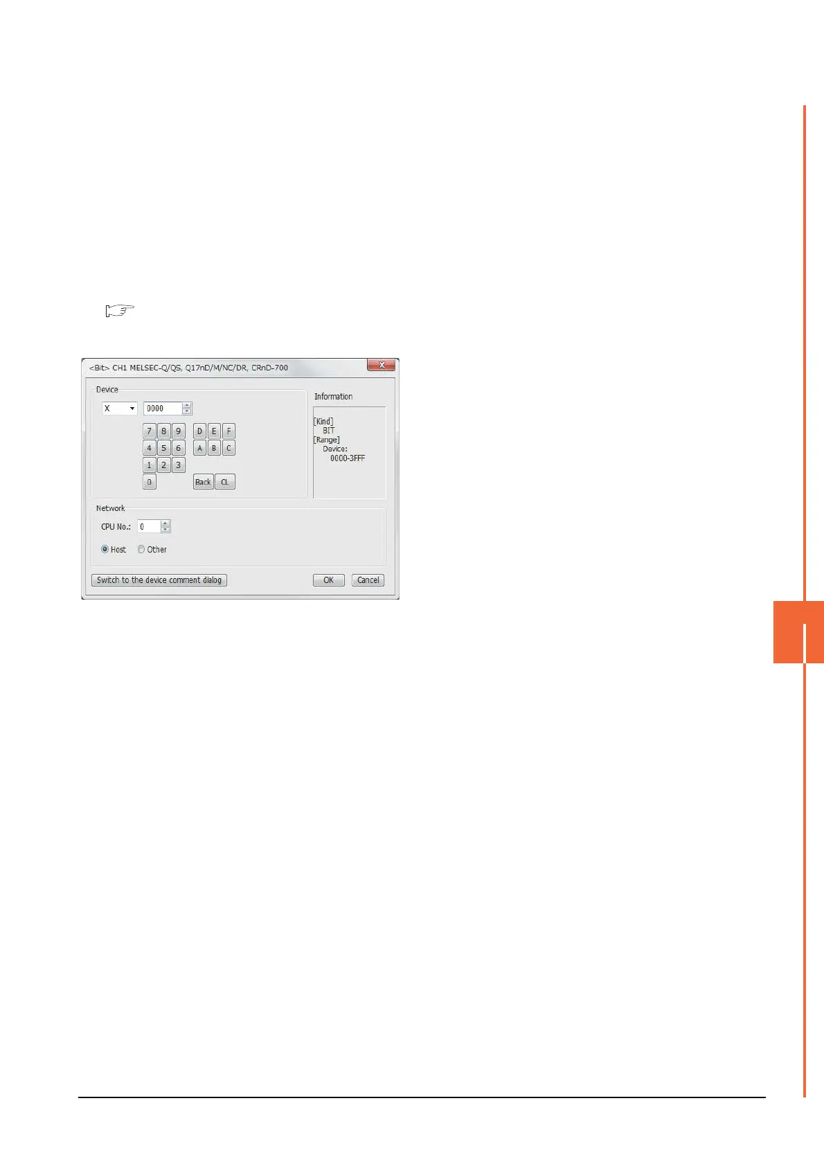
Set [CPU No.] to "2" in the device setting to monitor the
device of the Motion CPU area (CPU No.2).
When the CPU No. is set to "0" or "1", the device on the
PLC CPU area (CPU No.1) is monitored.
When the CPU No. is set to the number other than "0"
to "2", a communication error occurs and the monitoring
cannot be executed.
For setting the CPU No., refer to the following manual.
GT Designer3 (GOT2000) Help
Example) Setting dialog box of the bit device

Table of Contents

Other manuals for Mitsubishi GOT2000 Series

Questions and Answers:

Question and Answer IconNeed help?

Do you have a question about the Mitsubishi GOT2000 Series and is the answer not in the manual?

Mitsubishi GOT2000 Series Specifications

General IconGeneral
Power Supply24VDC
SoftwareGT Works3
ProcessorRISC CPU
InterfaceEthernet, USB, RS-232, RS-422/485
Operating Temperature0°C to 50°C
Display TypeTFT LCD
Storage Temperature-20°C to 60°C
Humidity10% to 90% (non-condensing)
Shock Resistance147 m/s² (15G), 11ms duration
Touch PanelAnalog Resistive

Related product manuals