EasyManuals Logo

Mitsubishi GOT2000 Series Connection Manual

Mitsubishi GOT2000 Series
674 pages
To Next Page IconTo Next Page
To Previous Page IconTo Previous Page
Page #347 background imageLoading...
Page #347 background image
11. CC-Link IE FIELD NETWORK CONNECTION
11.1 Connectable Model List
11 - 5
CC-Link IE FIELD NETWORK CONNECTION
11
(Continued to next page)
*1 Only the first step can be used on the extension base unit (Q52B/Q55B).
*2 For the PLC CPU area, use a module with the upper five digits later than 12012. Only the PLC CPU area can be monitored.
*3 The extension base unit (Q5 B/Q6 B) can be used.
Motion
controller
CPU
(Q Series)
Q172CPU
- -
Q173CPU
Q172CPUN
Q173CPUN
Q172HCPU
Q173HCPU
Q172DCPU
CC-Link IE
FIELD
NETWORK
o
-
Q173DCPU
Q172DCPU-S1
Q173DCPU-S1
Q172DSCPU
Q173DSCPU
Q170MCPU
*1
*2
11.2
Q170MSCPU
*3
Q170MSCPU-S1
*3
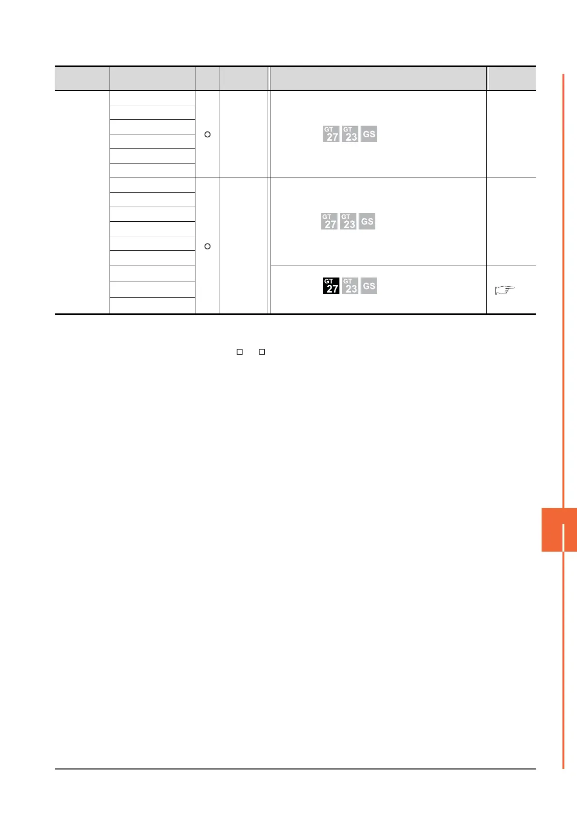
Series Model name Clock
Communication
type
Connectable model Refer to

Table of Contents

Other manuals for Mitsubishi GOT2000 Series

Questions and Answers:

Question and Answer IconNeed help?

Do you have a question about the Mitsubishi GOT2000 Series and is the answer not in the manual?

Mitsubishi GOT2000 Series Specifications

General IconGeneral
Power Supply24VDC
SoftwareGT Works3
ProcessorRISC CPU
InterfaceEthernet, USB, RS-232, RS-422/485
Operating Temperature0°C to 50°C
Display TypeTFT LCD
Storage Temperature-20°C to 60°C
Humidity10% to 90% (non-condensing)
Shock Resistance147 m/s² (15G), 11ms duration
Touch PanelAnalog Resistive

Related product manuals