1. PREPARATORY PROCEDURES FOR MONITORING
1.1 Setting the Communication Interface
1 - 11
1
PREPARATORY PROCEDURES FOR MONITORING
Setting item
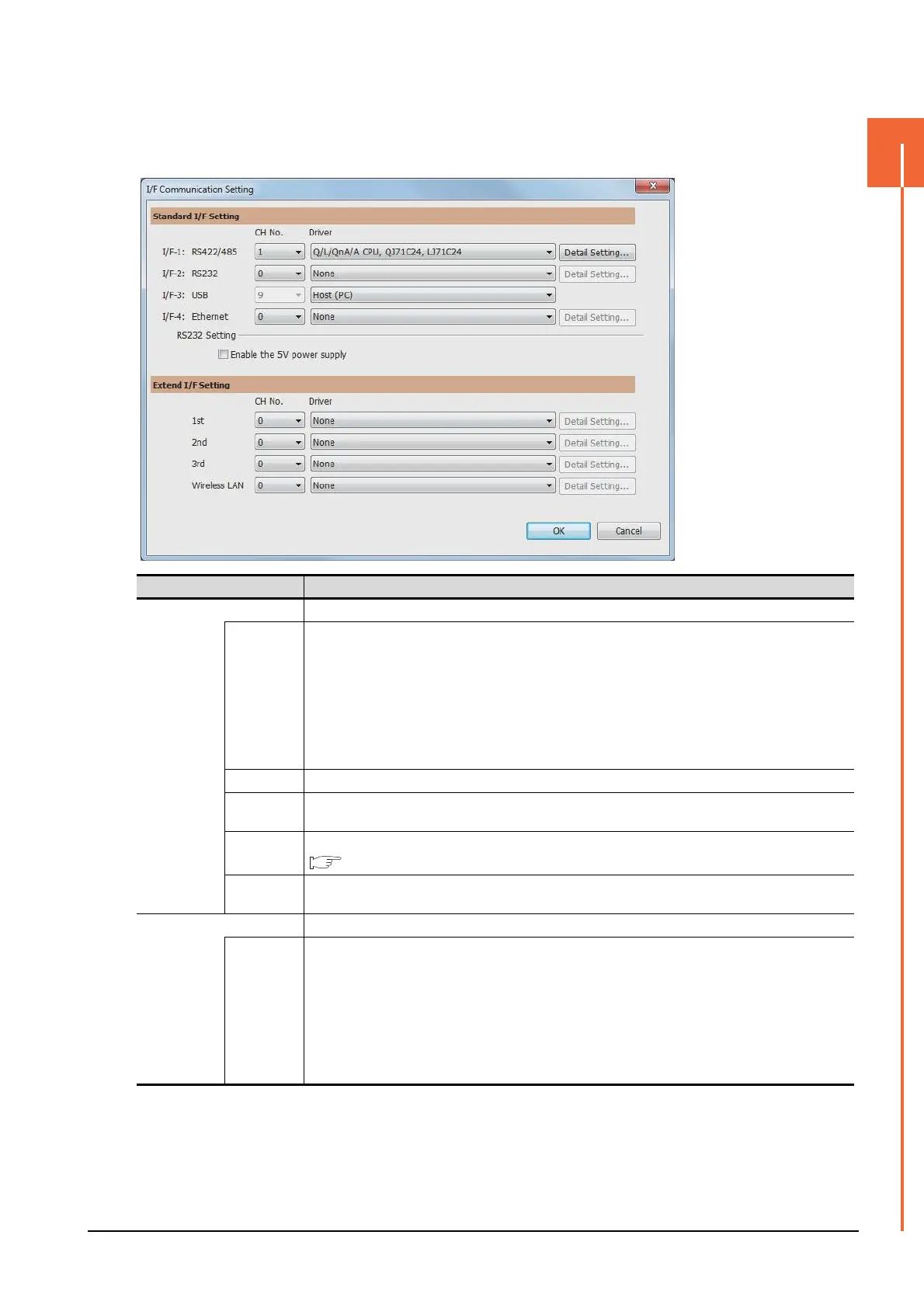
The following describes the setting items for the standard I/F setting and extension I/F setting.
Item Description
Standard I/F setting Set channel No. and drivers to the GOT standard interfaces.
CH No.
Set the CH No. according to the intended purpose.
0: Not used
1 to 4: Used for connecting a controller of channel No. 1 to 4 set in Setting connected equipment (Channel
setting)
5 to 8: Used for barcode function, RFID function, remote personal computer operation unction (serial)
9: Used for connecting Host (PC) or Ethernet download
A: Used for the report function (with a serial printer), hard copy function (with a serial printer), remote personal
computer operation function (Ethernet), VNC server function, gateway function, and MES interface function.
Multi: Used for multi-channel Ethernet connection
I/F The communication type of the GOT standard interface is displayed.
Driver
Set the driver for the device to be connected.
• None • Host (Personal computer) • Each communication driver for connected devices
Detail Setting
Make settings for the transmission speed and data length of the communication driver.
Refer to each chapter of the equipment to be connected to the GOT.
RS232
Setting
To validate the 5V power supply function in RS232, mark the [Enable the 5V power supply] checkbox.
The RS232 setting is invalid when the CH No. of [I/F-1: RS232] is [9].
Extension I/F setting Set the communication unit attached to the extension interface of the GOT.
CH No.
Set the CH No. according to the intended purpose.
The number of channels differs depending on the GOT to be used.
0: Not used
1 to 4: Used for connecting a controller of channel No. 1 to 4 set in Setting connected equipment (Channel
setting)
5 to 8: Used for barcode function, RFID function, remote personal computer operation (serial)
A: Used for the video/RGB display function, multimedia function, external I/O function, operation panel function,
RGB output function, report function, hard copy function (with a printer), sound output function, gateway
function, MES interface function, and wireless LAN connection.

 Loading...


