12 - 32
12. CC-Link CONNECTION (INTELLIGENT DEVICE STATION)
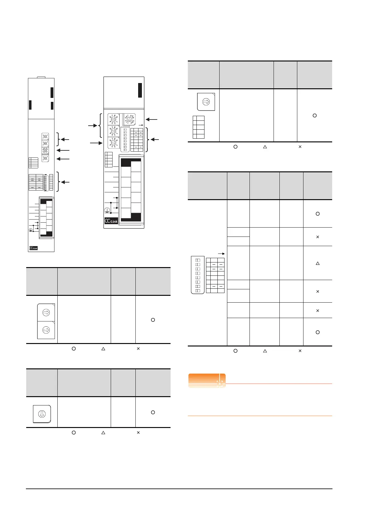
12.4 PLC Side Setting
Settings of CC-Link module (A Series)
Set for each setting switch.
(1) Station number setting switch
: Necessary : As necessary : Not necessary
(2) Mode setting switch
: Necessary : As necessary : Not necessary
(3) Transmission speed setting switch
: Necessary : As necessary : Not necessary
*1 Specify the same transmission speed as that of the GOT.
(4) Condition setting switches
: Necessary : As necessary : Not necessary
*2 Will be valid when the CC-Link module is a local station.
In the case of the master station, turn off it.
When the switch setting has been changed
Turn the PLC CPU OFF then ON again, or reset the
PLC CPU.
Station
number
setting switch
Description Set value
Setting
necessity at
GOT
connection
Station number setting
(master station)
0 (fixed)
Mode setting
switch
Description Set value
Setting
necessity at
GOT
connection
Mode setting
(Online: Remote net
mode)
0 (fixed)
AJ61BT11
(2)
(4)
(1)
(3)
A1SJ61BT11
(2)
(4)
(1)
(3)
A
J61BT11
E
R
R
O
R
R
A
T
E
B
T
E
S
T
1
B RATE
0 156K
1 625K
2 2. 5M
35M
4 10M
ON
MODE
0 : ONLINE (A. R. )
2 : OFFLINE
RUN
ERR.
MST
S MST
LOCAL
CPU R / W
SW
M / S
PRM
TIME
LINE
L RUN
L ERR.
OFF
S MSTM / L
HOLDCLEAR
3 / 41 / 2
SW
1
2
3
4
5
6
7
8
ON
10
8
6
4
2
9
7
5
3
1
NC
DA
NC
(FG)
SLD
NC
NC
NC
DB
DG
STATION NO.
10
x
x
156K
625K
2. 5M
5M
10M
TEST
S0
S1
S2
SD
RD
0
8
7
5
3
2
0
8
7
5
3
2
0
8
7
5
3
2
C
8
4
0
1 : ONLINE (RIM )
ISFM SFM
2 / 31 / 4
10
8
6
4
2
9
7
5
3
1
NC
DA
NC
(FG)
SLD
NC
NC
NC
DB
DG
A1SJ61BT11
A
1SJ61BT11
12345678
O N
STATION NO. MODE
10
x
1
x
B RATE
0 156K
1 625K
2 2. 5M
35M
4 10M
1
2
3
4
5
6
7
8
M / L
CLR
1/2
S. M
HLD
3/4
SW OFF ON
RUN
ERR.
MST
S MST
LOCAL
CPU R / W
L RUN
L ERR.
SD
RD
SW
M / S
PRM
TIME
LINE
E
R
R
O
R
0
5
0
5
0
5
C
8
4
0
ISM
SFM
1/4 2/3
10
x
1
x
0
1
9
8
7
6
5
4
3
2
0
1
9
8
7
6
5
4
3
2
STATION NO.
Transmission
speed setting
switch
Description Set value
Setting
necessity at
GOT
connection
Transmission speed
setting (156kbps)
*1
0
Condition setting
switches
Setting
switch
Description Set value
Setting
necessity at
GOT
connection
SW1
Station type
(Master
station/Local
station)
OFF
(fixed)
SW2
Not used
OFF
(fixed)
SW3
SW4
Input data
status of the
data link
error station
(clear)
OFF
SW5 Number of
stations
occupied
*2
OFF
(fixed)
SW6
SW7 Not used
OFF
(fixed)
SW8
Module
mode
(Intelligent
mode)
OFF
(fixed)
B RATE
0 156K
1 625K
2 2. 5M
35M
4 10M
0
1
9
8
7
6
5
4
3
2
12345678
O N
1
2
3
4
5
6
7
8
M / L
CLR
1/2
S. M
HLD
3/4
SW OFF ON
ISM
SFM
1/4 2/3

 Loading...


