14. INVERTER CONNECTION
14.3 Connection Diagram
14 - 19
INVERTER CONNECTION
14
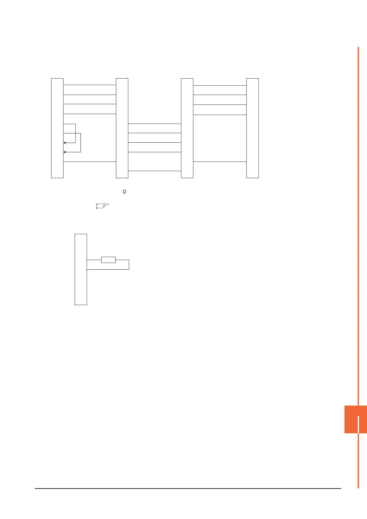
*1 Turn ON (100 ) the terminator switch for the most distant FR-E7TR from the GOT.
*2 Set the terminating resistor of GOT side, which will be a terminal, to "Enable"
1.4.3 Terminating resistors of GOT
(8) RS485 connection diagram 8)
RDA
RDB
SDA
SDB
RSA
RSB
CSA
CSB
SG
FG
SDB
SDA
RDB
RDA
SG
SDA
SDB
RDA
RDB
SG
2
7
1
6
3
8
4
9
5
-
SDA
SDB
RDA
RDB
SG
SDB
SDA
RDB
RDA
SG
SDA
SDB
RDA
RDB
SDB
SDA
RDB
RDA
SG
SG
GOT side
*
2
FR-E7TR side
terminal block
Station No.0
FR-E7TR side
terminal block
Station No.1
FR-E7TR side
terminal block
*
1
Station No.2
(9) RS485 connection diagram 9)
Distributor side
Terminating resistor
100Ω 1/2W
SDA
SDB
RDA
RDB
P5S
P5S
SG
5
4
3
6
2
8
1

 Loading...


