14. INVERTER CONNECTION
14.6 Device Range that Can Be Set
14 - 47
INVERTER CONNECTION
14
*4 Only writing is possible for WS devices.
More than one WS cannot turn on at once.
(Except the turned on WS device, the other WS devices turn
off.)
Bits of SP122 (word device) and SP121 (word device) are
assigned to WS0 to WS7 and WS8 to WS15 respectively.
When more than one WS turns on at once, convert the
values for the bit devices that are assigned to the word
device into values for the word device. Write the converted
values into SP122 or SP121.
• Setting High speed operation command (WS5), Middle
speed operation command (WS4), and Low speed
operation command (WS3)
When setting High speed operation command (WS5),
Middle speed operation command (WS4), and Low speed
operation command (WS3), write numerical values to
device SP122 as necessary.
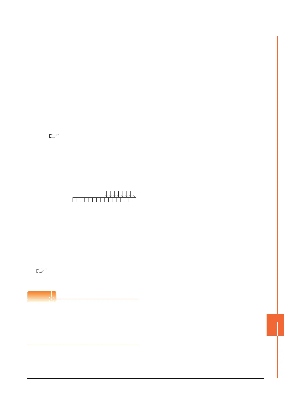
As the following figure shows, each operation mode is
assigned to device SP122.
The following shows an example for Forward rotation
command (WS1) and Low speed operation command
(WS3).
*5 The SM device cannot be specified as a word device.
For the applicable SM devices, refer to the following.
A800 PLC FUNCTION PROGRAMMING MANUAL
Write [1] to each bit corresponding to Forward rotation
command (WS1) and Low speed operation command
(WS3) of device SP122. The value will be 000AH in this
example. When writing the value to device SP122 actually,
convert 000AH to decimal number and write the value
[10].
When using a WS device, [Alternate] of a bit switch cannot
be used.
Use [Momentary], [Set], and [Reset] for bit switch actions.
For the correspondences between the virtual inverter
devices used in the GOT and the data of the inverter,
refer to the following.
User's Manual of the used inverter
(communication function (setting item and set
data))
If the automatic connection fails
When [Automatic Negotiation] is set to [Yes] in the
GOT communication settings, the inverter parameters
are reconfigured within the user-specified negotiation
time.
If the automatic connection fails, set the longer
negotiation time with GT Designer3 or the utility.
Device SP122
b15 b7 b0
0000000000001010
WS7: Output stop(MRS)
WS6: Second function selection(RT)
WS5: High speed operation command(RH)
WS4: Middle speed operation command(RM)
WS3: Low speed operation command(RL)
WS2: Reverse rotation command(STR)
WS1: Forward rotation command(STF)
WS0: Current input selection(AU)

 Loading...


