14 - 46
14. INVERTER CONNECTION
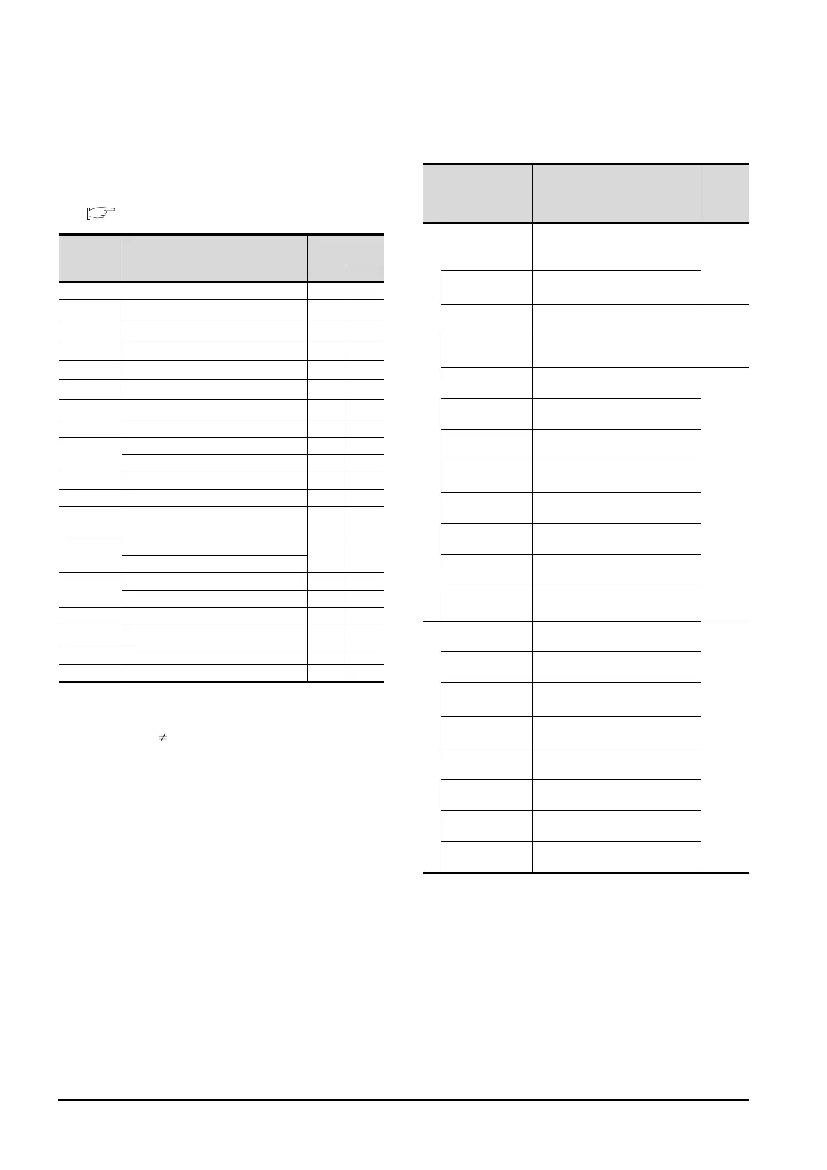
14.6 Device Range that Can Be Set
(7) Special parameter
The numbers of the inverter’s virtual devices (SP) used
for the GOT correspond to instruction codes of the
inverter communication function.
For instruction details, and values to be read and
written, refer to the following,
Manual of the inverter used
*1 GOT cannot monitor SP109 to SP111 if the conditions below
are satisfied at the same time.
(Only FREQROL-E500/S500(E)/F500J/D700/F700PJ/E700
series)
•Pr37 0
• SP127 = 1
*2 Only reading is possible for SP111 to SP114.
These devices cannot be used for a write object (numerical
input etc.).
*3 Only writing is possible for SP124 and SP125.
These devices cannot be used for read object.
Inverter (FREQROL 800 series)
(Automatic connection)
*1 Only 16-bit (1-word) designation is possible.
*2 Only reading is possible.
*3 When the GOT is connected to the PU connector and the
operation mode is set to the PU operation mode, the multi-
speed operation (W3 to W7, SP121, SP122) cannot be used.
For using the multi-speed operation, follow either of the
operations as below.
• Connect the GOT to the RS-485 terminal and set the
operation mode to the NET operation mode (Computer
link operation mode), and then operate the inverter.
• Change the motor speed with the set frequency (SP109,
SP110), and then operate the inverter with the forward or
reverse rotation (WS1, WS2, SP121, SP122).
Device
name
Description
Instruction
code
Read Write
SP108 Second parameter changing 6C
H ECH
SP109
*1
Set frequency (RAM) 6DH EDH
SP110
*1
Set frequency (RAM, E
2
PROM)
6EH EEH
SP111
*1*2
Output frequency 6FH -
SP112
*2
Output current 70H -
SP113
*2
Output voltage 71H -
SP114
*2
Special monitor 72H -
SP115 Special monitor selection No. 73H F3H
SP116
Alarm definition all clear - F4
H
Latest alarm, second alarm in past 74H -
SP117 Third alarm in past, fourth alarm in past 75
H -
SP118 Fifth alarm in past, sixth alarm in past 76
H -
SP119
Seventh alarm in past, eights alarm in
past
77
H -
SP121
Inverter status monitor (extended)
79
H F9H
Run command (extend)
SP122
Inverter status monitor 7A
H -
Run command - FA
H
SP123 Communication mode 7BH FBH
SP124
*3
All parameter clear - FCH
SP125
*3
Inverter reset - FDH
SP127 Link parameter extended setting 7FH FFH
Device name Setting range
Device
No.
represen
tation
Bit device
Inverter
status monitor
(RS)
*2
0-0 RS0 to 0-31 RS15
0-100 RS0 to 0-115 RS15
Decimal
Run command
(WS)
*3*4
0-0 WS0 to 0-31 WS15
0-100 WS0 to 0-115 WS15
Input (X)
0-0 X00 to 0-31 X7F
0-100 X00 to 0-115 X7F
Hexadec
imal
Output (Y)
0-0 Y00 to 0-31 Y7F
0-100 Y00 to 0-115 Y7F
Internal relay (M)
0-0 M0 to 0-31 M127
0-100 M0 to 0-115 M127
Decimal
Timer Coil (TC)
0-0 TC0 to 0-31 TC15
0-100 TC0 to 0-115 TC15
Timer Contact (TT)
0-0 TT0 to 0-31 TT15
0-100 TT0 to 0-115 TT15
Counter Coil (CC)
0-0 CC0 to 0-31 CC15
0-100 CC0 to 0-115 CC15
Counter Contact
(CT)
0-0 CT0 to 0-31 CT15
0-100 CT0 to 0-115 CT15
Retentive timer
Coil (SC)
0-0 SC0 to 0-31 SC15
0-100 SC0 to 0-115 SC15
Retentive timer
Contact (SS)
0-0 SS0 to 0-31 SS15
0-100 SS0 to 0-115 SS15
Special relay
(SM)
*5
0-0 SM0 to 0-31 SM2047
0-100 SM0 to 0-115 SM2047
Word device
Alarm definition (A)
*1*2
0-0 A0 to 0-31 A7
0-100 A0 to 0-115 A7
Decimal
Parameter (Pr)
*1
0-0 Pr0 to 0-31 Pr1500
0-100 Pr0 to 0-115 Pr1500
Special parameter
(SP)
*1*3
0-0 SP108 to 0-31 SP127
0-100 SP108 to 0-115 SP127
Timer current value
(TN)
0-0 TN0 to 0-31 TN15
0-100 TN0 to 0-115 TN15
Counter current
value (CN)
0-0 CN0 to 0-31 CN15
0-100 CN0 to 0-115 CN15
Retentive timer
current value (SN)
0-0 SN0 to 0-31 SN15
0-100 SN0 to 0-115 SN15
Data register (D)
0-0 D0 to 0-31 D255
0-100 D0 to 0-115 D255
Special data
register (SD)
0-0 SD0 to 0-31 SD2047
0-100 SD0 to 0-115 SD2047

 Loading...


