20. FA TRANSPARENT FUNCTION
20.4 System Configuration
20 - 21
20
FA TRANSPARENT FUNCTION
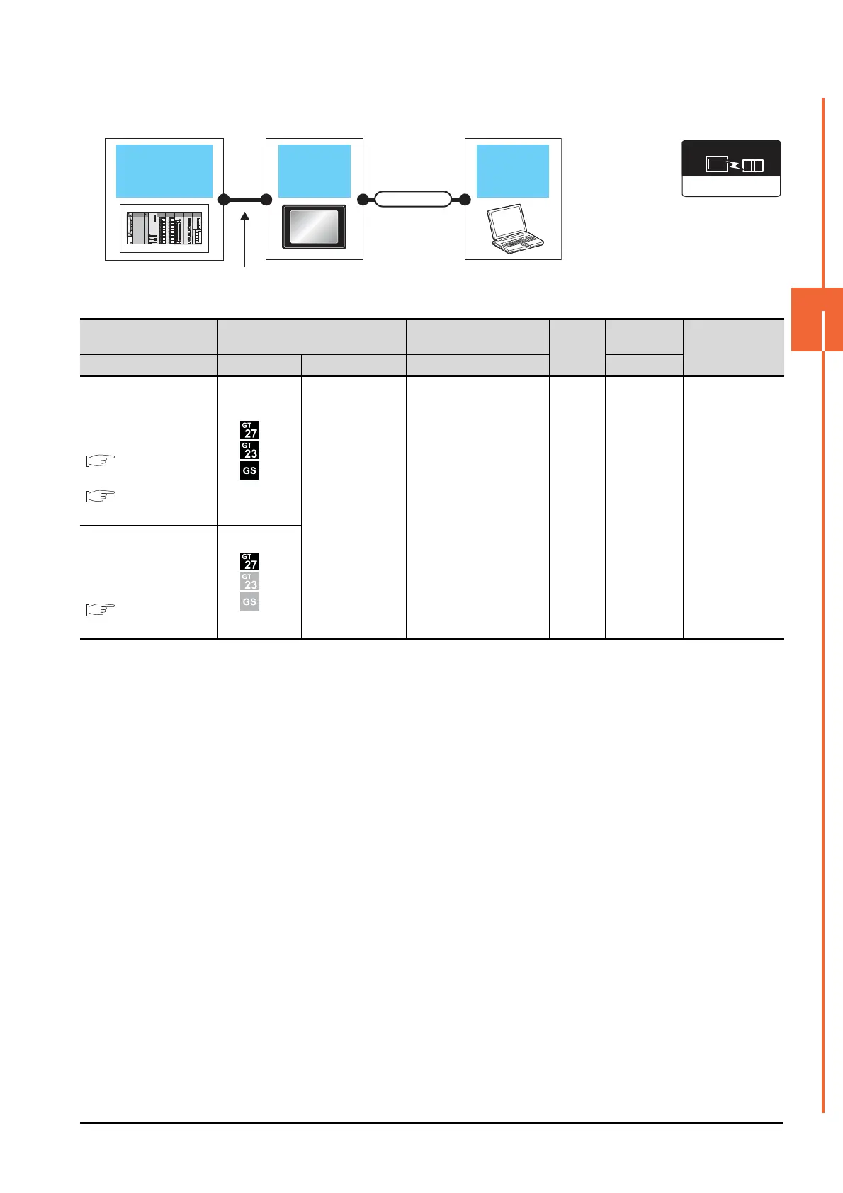
When connecting the GOT and the personal computer by Ethernet
*1 The destination connected with the twisted pair cable varies with the configuration of the applicable Ethernet network system.
Connect to the Ethernet module, hub, transceiver, or other system equipment corresponding to the applicable Ethernet network
system.
Use cables, connectors, and hubs that meet the IEEE802.3 10BASE-T/100BASE-TX standards.
A cross cable is available for connecting the GOT to the Ethernet module.
*2 A length between a hub and a node.
The maximum distance differs depending on the Ethernet device to be used.
The following shows the number of the connectable nodes when a repeater hub is used.
• 10BASE-T: Max. 4 nodes for a cascade connection (500m)
• 100BASE-TX: Max. 2 nodes for a cascade connection (205m)
When switching hubs are used, the cascade connection between the switching hubs has no logical limit for the number of
cascades.
For the limit, contact the switching hub manufacturer.
*3 LCPU is not applicable to the bus connection.
*4 Not applicable to Setting/Monitoring tool for C Controller module.
Connection type
dependant
Communication driver
GOT
PC
PLC
Varies according to
the connection type.
Connection cable
PLC GOT
Connection cable
*1
Maximum
segment
length
*2
Personal
computer
Number of
connectable
equipment
Connection type Model Interface Cable model Software
For the system configuration
between
the GOT and PLC, refer to
the following.
DIRECT
CONNECTION TO CPU
*4
COMPUTER LINK
CONNECTION
*4
- (Built into GOT)
Twisted pair cable
• 10BASE-T
Shielded twisted pair cable
(STP) or unshielded
twisted pair cable (UTP):
Category 3, 4, and 5
• 100BASE-TX
Shielded twisted pair cable
(STP):
Category 5 and 5e
100m
GX Works2
Setting/
Monitoring tool
for C Controller
module
1 personal
computer
for 1 GOT
For the system configuration
between
the GOT and PLC, refer to
the following.
BUS
CONNECTION
*3

 Loading...


