ValueJet 1304 Service manual
4-93 AP-74109 Rev 1.1
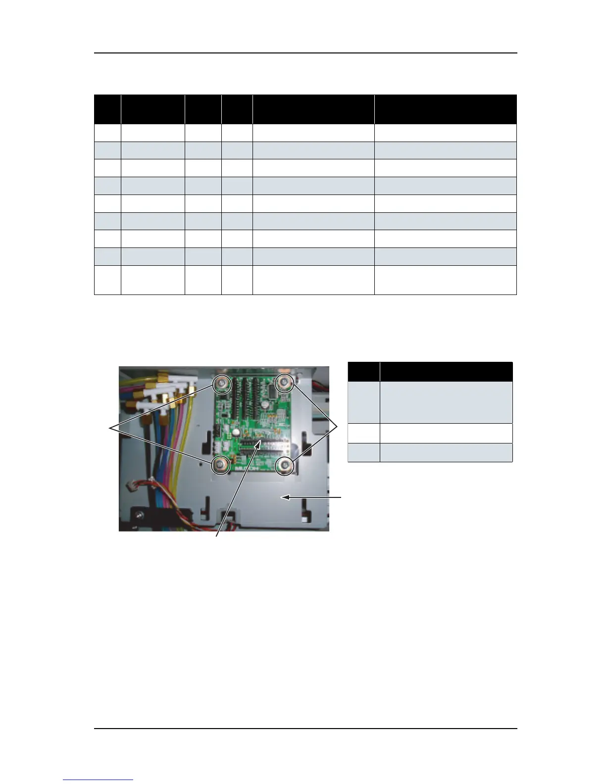
2. Remove the CR board assembly-retaining screw (tapping screw M3 × 8, S tight cup: 4).
3. Replace the CR board assembly.
4. To reassemble the unit, reverse the removal procedure.
Table 4-106 Connectors to CR Board Assembly
No. Connector
No.
# of
pins
Color Connect to Remarks
1J204
31 pins Black
Print head Connected to J1.
2 J205
31 pins Black
Print head Connected to J2.
3J201
31 pins Black
Main board assembly Connected to J11.
4 J202
31 pins Black
Main board assembly Connected to J10.
5J203
31 pins Black
Main board assembly Connected to J9.
6 J207
4 pins White
CR_ENC assembly
7J206
2 pins White
Cutter solenoid assembly
8 J208
4 pins Black
P_EDGE sensor assembly
9J209
3 pins White
PG origin point sensor
assembly
表 4-107
No. Part name
1 CR board screw
(tapping screw M3
× 8, S tight
cup)
2
CR board
3 CR board mounting plate