ValueJet 1304 Service manual
AP-74109 Rev 1.1 4-36
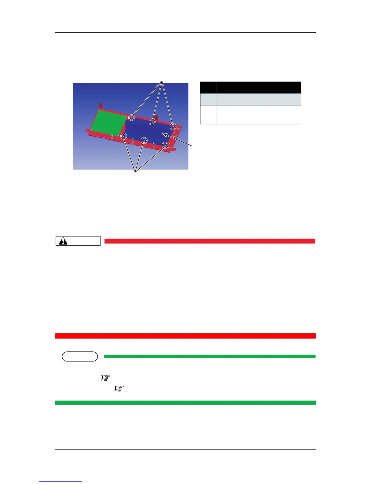
5. Remove the relay board assembly retaining screws (cup screw M3 × 6 white: 9).
6. Replace the relay board assembly.
7. To reassemble the unit, reverse the removal procedure.
4.3.6 Replacing Power Board Assembly
• When removing the power board assembly, remove the power cable and wait for at least
5 minutes before taking it out; this will discharge the residual electrical charge of the
electrolytic capacitor.
If you handle these boards before the capacitor charge is fully discharged, you may suffer
electric shock.
• To avoid electric shock, never touch the back of the power board.When handling the
power board, take the side of the board.
• To avoid a short circuit, do not place the power board assembly directly on conductive
objects.
Before replacing the power board assembly, remove the following parts.
• Rear cover: "4.2.8 Removing Media Guide R2" p.4-17
• Connector panel: "4.3.1 Removing Connector Panel and Cooling Fan" p.4-23
表 4-36
No. Part name
1 Relay board assembly
2
Relay board assembly screw
(cup screw M3
× 6 white)