ValueJet 1304 Service manual
4-67 AP-74109 Rev 1.1
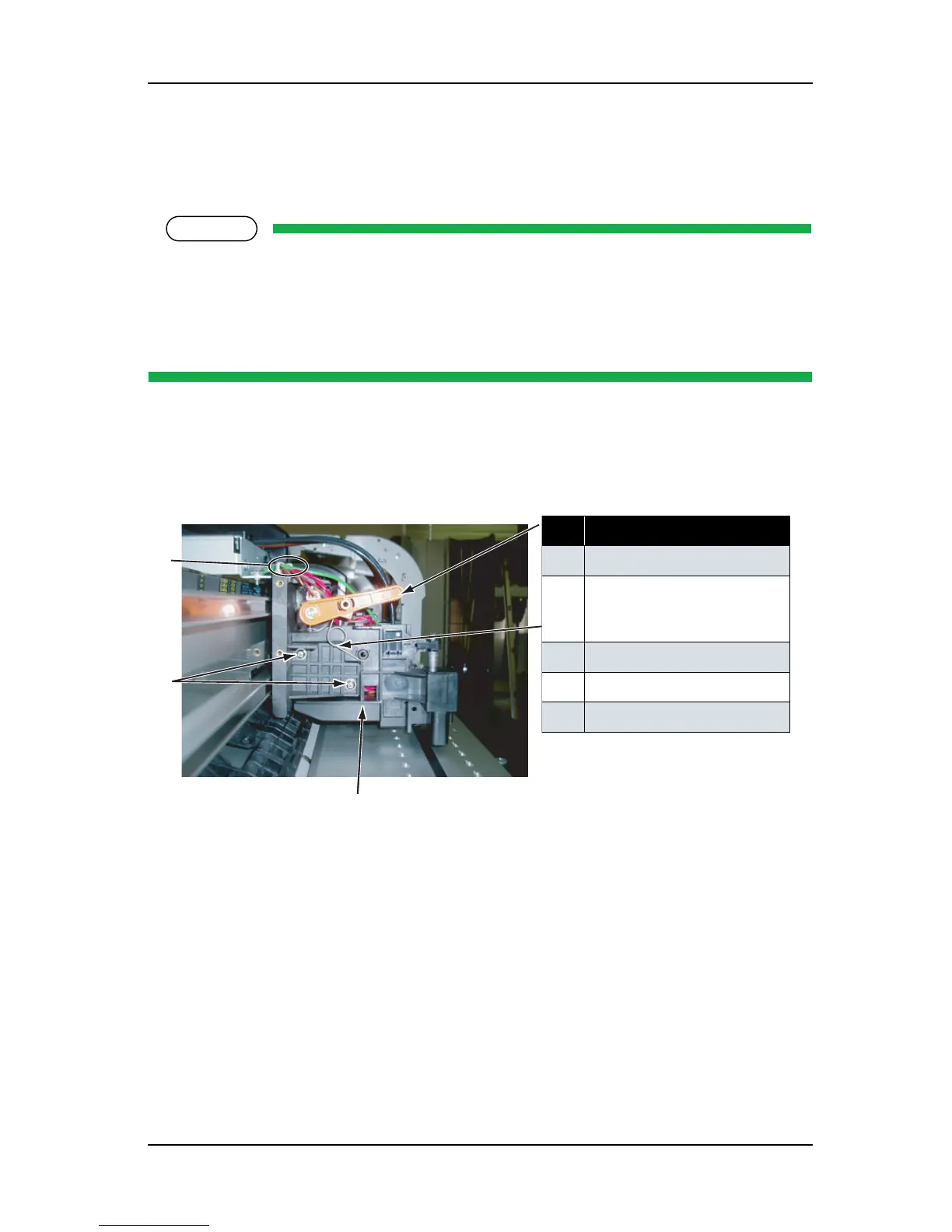
4.6.2 Replacing Cutter Holder Assembly
(1) Replacing Cutter Holder Assembly
Before replacing parts in the cutter holder assembly, remove the following parts referring to the
instructions shown below.
Removing the cable cover L, R: refer to "4.6.1 Replacing Print Head" p.4-61
Removing the P_EDGE sensor, cutter sensor connector: refer to "4.10.1 Replacing CR Board
Assembly" p.4-91
1. Release the sensor cables in the front of the cutter holder assembly from the clamps (3 points) on the front
of the cutter holder assembly.
2. Remove the height adjusting lever spring from the height adjusting lever.
3. Remove the cutter holder-retaining screw (round head spring screw M3
× 8 W sems: 2).
4. Remove the cutter holder assembly from the carriage.
5. Replace the parts.
6. To reassemble the unit, reverse the removal procedure.
7. Perform adjustments by following the instructions in "7.2 Adjustment Item" p.7-3.
表 4-76
No. Part name
1 Clamp
2
Cutter holder assembly screw
(round head spring screw M3
×
8 W sems)
3 Cutter holder assembly
4 Height adjusting lever screw
5 Height adjusting lever