ValueJet 1304 Service manual
AP-74109 Rev 1.1 4-92
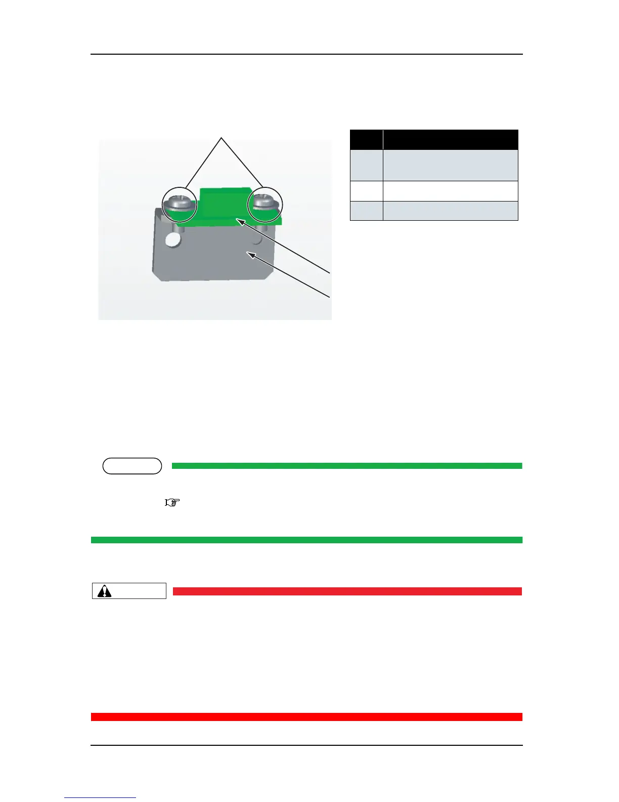
5. Replace the P_REAR sensor assembly.
6. To reassemble the unit, reverse the removal procedure.
4.10 Replacement of Cable Guide Section Components
4.10.1 Replacing CR Board Assembly
Before replacing CR board assembly, remove the following covers.
•Top cover: "4.2.6 Removing Top Cover" p.4-15
• CR board cover: refer to the instructions up to step 4 in "4.6.1 Replacing Print Head" p.4-61.
1. Remove the following connectors from the CR board assembly.
• Before replacing board or connecting/removing tape wire (FFC), unplug the power cable
and leave the printer for a while. Or board may be damaged by overcurrent.
• When connecting or removing the FFC type cables to the CR board assembly connector,
always pull or push the cables perpendicularly to the connector.
Pulling or pushing the wire slantwise may damage/short/break the terminals in the
connectors, resulting in a breakdown of the on-board elements.
• You can connect/remove the tape wire up to five times.
表 4-105
No. Part name
1 P_REAR sensor assembly
screw (cup screw M2
× 6)
2
P_REAR sensor assembly
3 PE sensor plate
1
2
3