ValueJet 1304 Service manual
4-121 AP-74109 Rev 1.1
4.12.7 Replacing Peripheral Devices of VJ Take Up Unit Motor Assembly
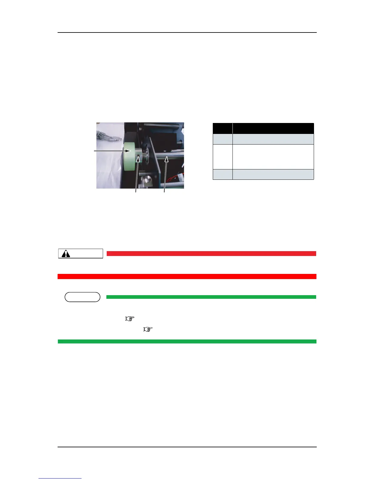
(1) Replacing Drive Roller
1. Remove the flat head screws (set screw (top cup point) M4 × 6: 2 pieces) that retain the drive roller on
the drive axis C.
2. Remove the drive roller.
3. To reassemble the unit, reverse the removal procedure.
(2) Replacing VJ Take Up Unit Motor Assembly
Remove the following parts before replacing the VJ take up unit motor assembly.
• Take Up Unit cover: "4.12.3 Removing Take Up Unit Cover" p.4-105
• Screw for the board chassis: "(1) Removing Board Chassis" p.4-109
表 4-150
No. Part name
1 Drive roller
2 Screws that retain the drive
roller (set screw (top cup point)
M4
× 6)
3 Drive axis C
3
1
2