Before replacing the heater junction board, remove the parts as follows.
"4.2.1 Removing R Side Cover" p.4-6
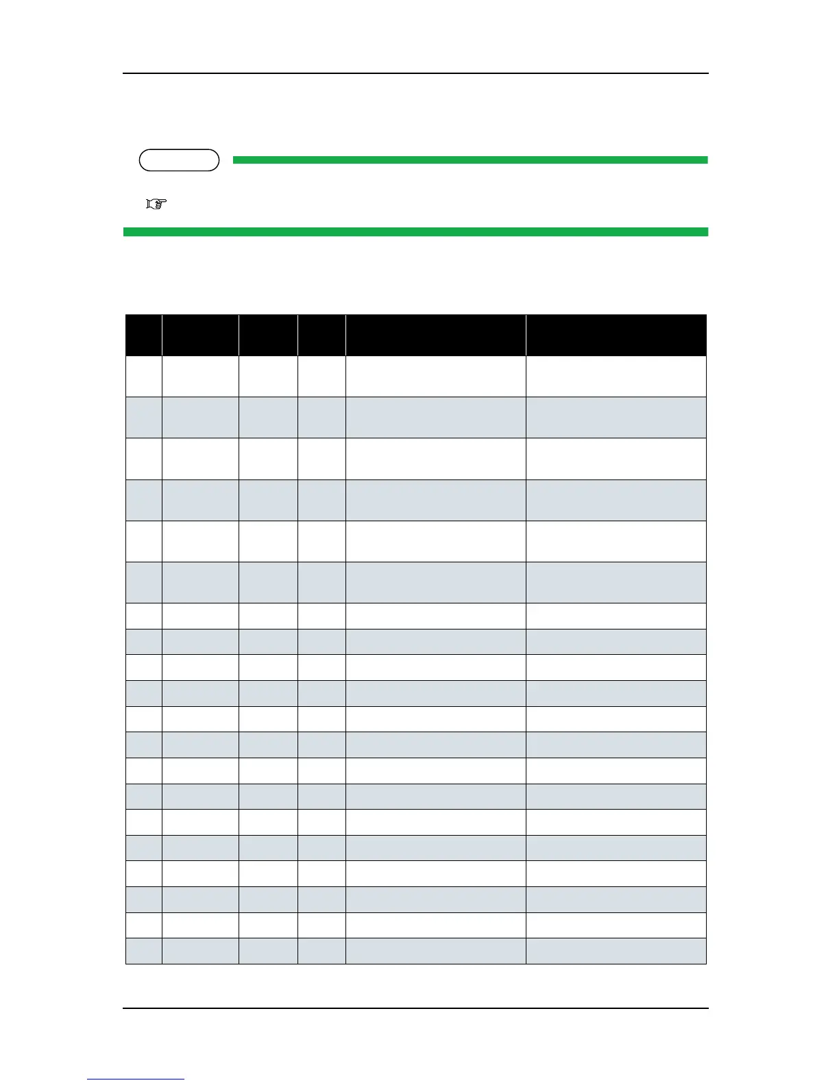
1. Remove the following connectors shown in the table below from the heater junction board.
Table 4-100 Connectors to Heater junction board
No. Connector
No.
# of
pins
Color Connect to Remarks
1 J2 4 White HEATER CONT board Connected to J8 by using power
cable between CNT - JC.
2 J3 - - HEATER CONT board Connected to J9 by using serial
cable between MAIN - CNT.
3 J5 10 White INK K Connected with INK cable
assembly (VJ12).
4 J6 10 White INK C Connected with INK cable
assembly (VJ12).
5 J7 10 White INK M Connected with INK cable
assembly (VJ12).
6 J8 10 White INK Y Connected with INK cable
assembly (VJ12).
7 J9 - - - Unused
8 J10 - - Unused
9 J11 - - - Unused
10 J12 - - - Unused
11 J13 - - - Unused
12 J14 - - - Unused
13 J15 - - - Unused
14 J16 - - - Unused
15 J17 - - - Unused
16 J18 - - - Unused
17 J19
- - - Unused
18 J20 - - - Unused
19 J21 -
- - Unused
20 J22 - - - Unused