ValueJet 1304 Service manual
4-37 AP-74109 Rev 1.1
1. Remove the following connector from the power board assembly.
2. Remove the following connector from the HEATER-CONT board.
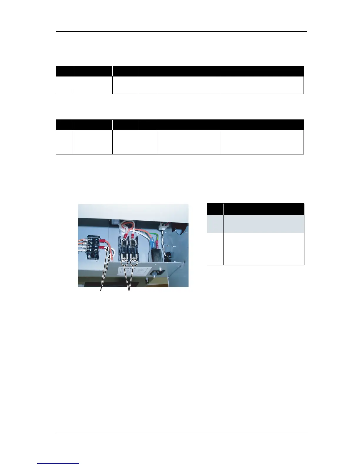
3. Remove the fuse-side two screws (pan head small screw M4 × 6) retaining Fuse to terminal block AC
cable assembly, and remove the assembly.
Table 4-37 Connectors to Power Board Assembly
No. Connector No. # of pins Color Connect to Remarks
1 CN301 - White Main board assembly Connected to J1 by using DC cable
assembly.
Table 4-38 Connectors to HEATER-CONT Board Assembly
No. Connector No. # of pins Color Connect to Remarks
1 J22 - White Terminal Connected to terminal block by
using Terminal block to CNT AC
cable assembly
表 4-39
No. Part name
1 Fuse to terminal block AC cable
assembly
2
Screws retaining Fuse to
terminal block AC cable
assembly to fuse holder
(pan head small screw M4
× 6)