3.5.13 Replacing JUNC_FFC 89
3.5 Replacing Board Base section VJ628XE-M-00
3.5.13 Replacing JUNC_FFC
● Tools & Jigs & Maintenance part
• Before replacing Board Assy and pulling or pushing FFC type cables, unplug
Power cable and leave it for a while.
If operating with Power cable still plugged, Board may be damaged or operators
may get an electric shock by residual electric charge.
• When you handle Circuit board, do not touch any elements on it with bare hands.
Doing so may cause electrostatic discharge and damage the elements.
• Before plugging FFC, check the condition of FFC terminals (that the corners of
the terminals are not crooked and reinforcing plate is not peeled).
• Plug/unplug FFC perpendicularly to the connector. Never plug/unplug it
obliquely. If plugged obliquely, it may damage/shorten/break terminals in
connectors, causing a breakdown of on-board devices.
• Make sure to plug FFC all the way in the connector. After plugging it, make sure
that FFC and the connector terminals are not misaligned sideways and that FFC
is not plugged obliquely.
• This section describes the procedure to replace the maintenance part, Head
Cable Assy(DF-49017)and JUNC_FFC Assy.
• The replacement procedure is common to both R side and L side.The procedure
described here is that of R side.
Name No. Remarks
Head Cable Assy DF-49017 Exploded View Board Box
(for R)
JUNC_FFCAssy DG-44716 Exploded View Board Box
(for L)
Phillips screwdriver No.2 Generic
products
-
1 Remove Top Cover.
3.2.1 Removing Top Cover
2 Remove R Side Cover or L Side Cover.
3.2.2 Removing Side Cover
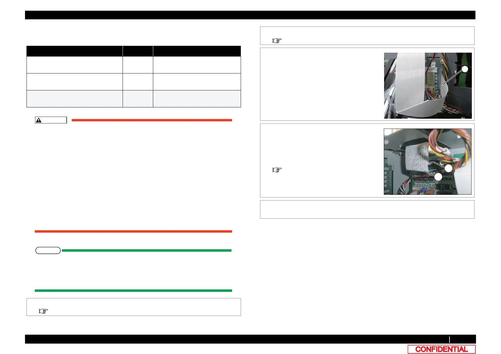
3 Remove JUNC_FFC from JUNCTION Board.
A : JUNC_FFC
4 Remove JUNC_FFC from the clamps on th e
path.
5 Remove JUNC_FFC from MAIN board.
A : JUNC_FFC(R side: J19)
B : JUNC_FFC(L side: J18)
6 Replacing JUNC_FFC.
Folding Direction JUNC FFC
7 To reassemble unit, reverse the removal
procedure.