Common Measurement Settings
R&S
®
FSW
362User Manual 1173.9411.02 ─ 43
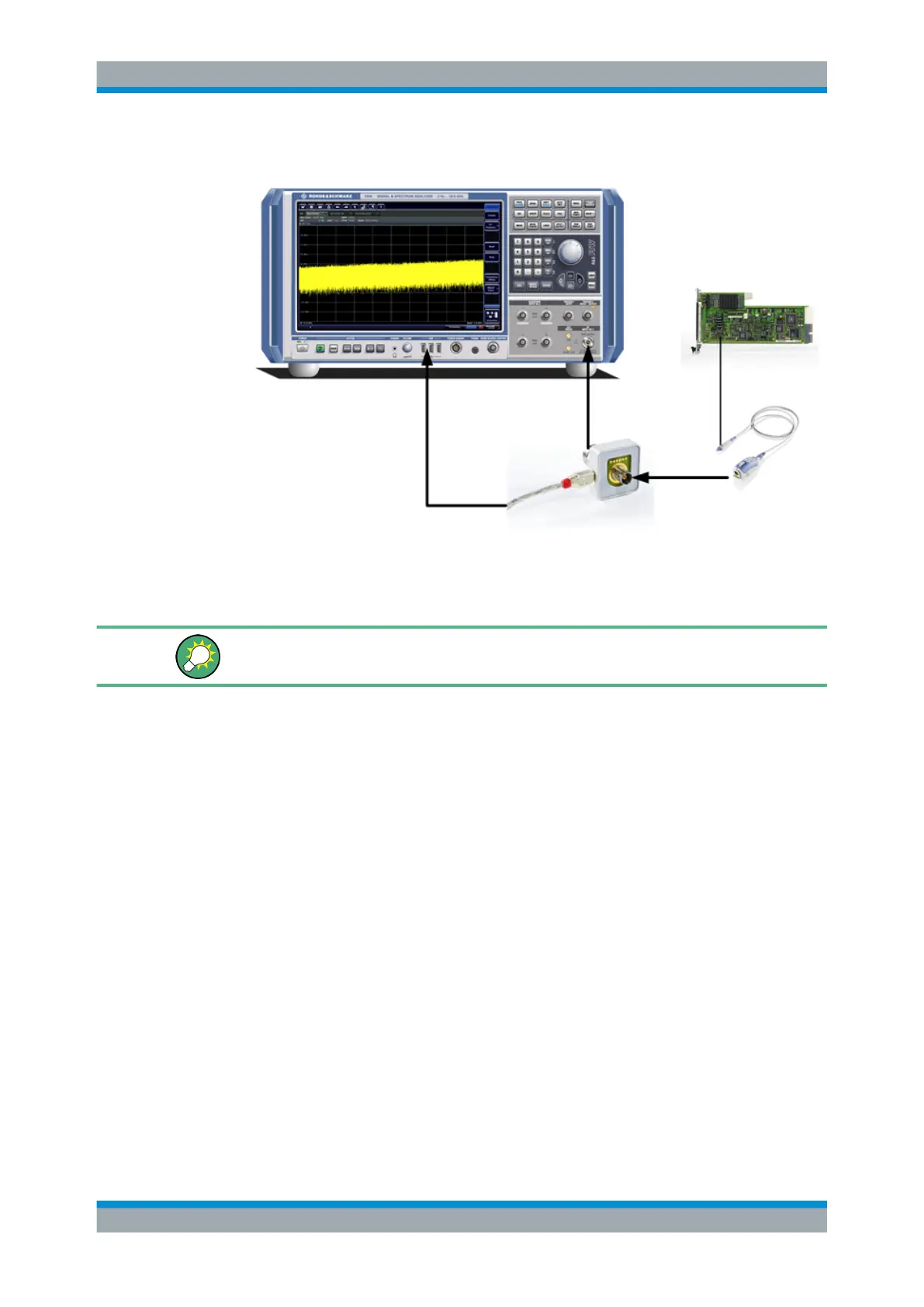
3. Connect the probe to the adapter.
Probes are automatically detected when you plug them into the R&S FSW. The
detected information on the probe is displayed in the "Probes" tab of the "Input"
dialog box.
To determine whether the probe has been connected properly and recognized by the
R&S FSW, use the [SENSe:]PROBe<pb>:SETup:STATe? remote control command.
Impedance and attenuation
The measured signal from the probe is attenuated internally by the probe's specific
attenuation. For RF probes, the attenuation is compensated using a pre-defined "Probe
on RF Input" transducer factor, which is automatically activated before the common RF
data processing. The reference level is adjusted automatically.
A fixed impedance of 50 Ω is used for all probes to convert voltage values to power
levels.
MultiMode Function and Offset Compensation for Modular RF Probes
The R&S RT-ZM probe family features the MultiMode function which allows you to
switch between single-ended, differential, and common mode measurements without
reconnecting or resoldering the probe.
Four different input voltages can be measured with the MultiMode feature:
●
P-Mode: (pos.) Single-ended input voltage (V
p
)
Voltage between the positive input terminal and ground
●
N-Mode: (neg.) Single-ended input voltage (V
n
)
Voltage between the negative input terminal and ground
●
DM-Mode: Differential mode input voltage (V
dm
)
Voltage between the positive and negative input terminal
Data Input and Output

 Loading...


