Common Measurement Settings
R&S
®
FSW
437User Manual 1173.9411.02 ─ 43
Data Output.................................................................................................................437
Noise Source Control..................................................................................................438
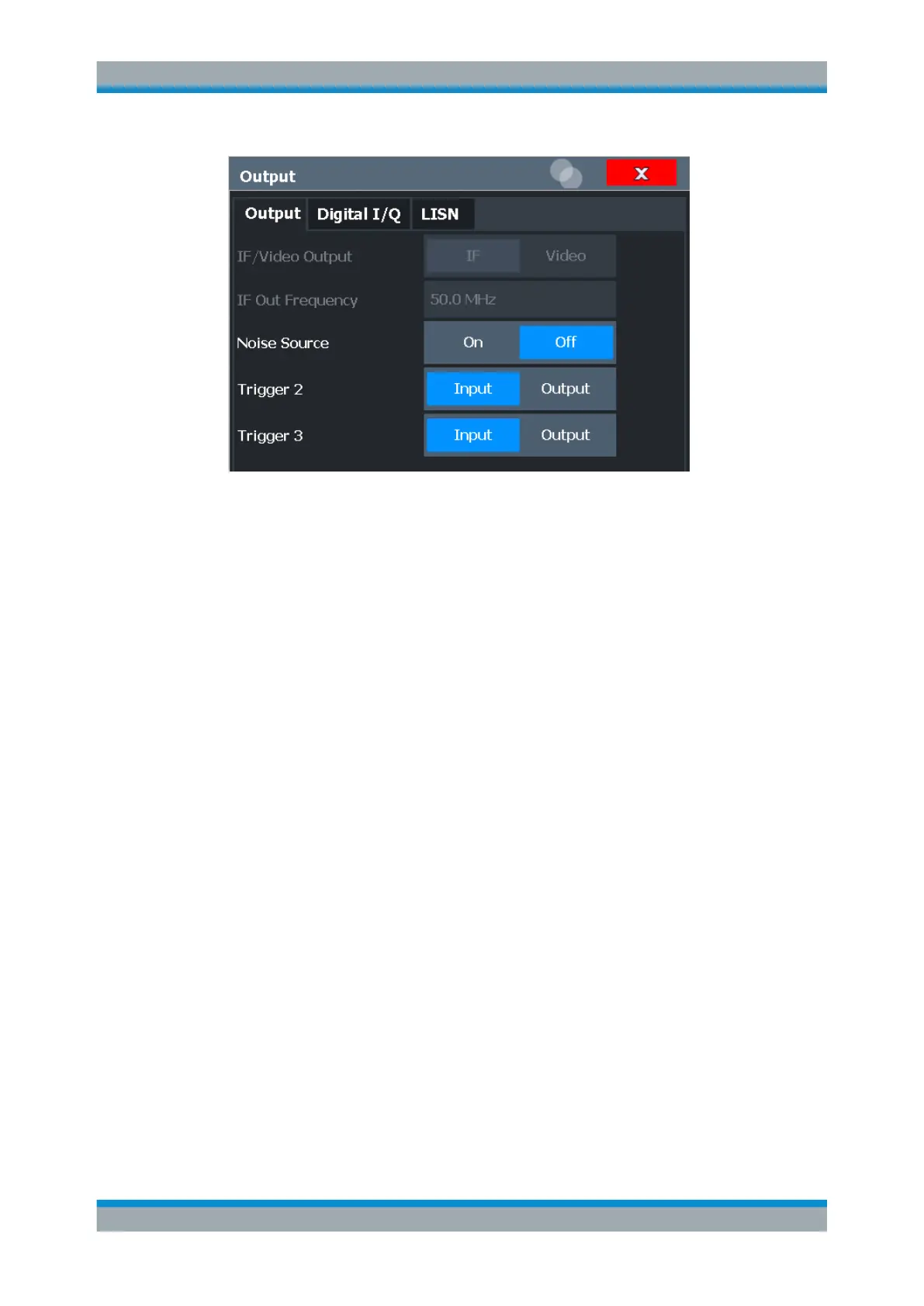
Data Output
Defines the type of signal available at one of the output connectors of the R&S FSW.
For restrictions and additional information, see Chapter 8.2.1.3, "IF and Video Signal
Output", on page 364.
"IF"
The measured IF value is provided at the IF/VIDEO/DEMOD output
connector.
For bandwidths up to 80 MHZ, the IF output is provided at the speci-
fied "IF Out Frequency".
If an optional bandwidth extension R&S FSW-B160/-B320/-B512 is
used, the measured IF value is available at the "IF WIDE OUTPUT"
connector. The frequency at which this value is output is determined
automatically. It is displayed as the "IF Wide Out Frequency". For
details on the used frequencies, see the data sheet.
This setting is not available for bandwidths larger than 512 MHz.
"2ND IF"
The measured IF value is provided at the "IF OUT 2 GHz/ IF OUT
5 GHz" output connector, if available, at a frequency of 2 GHz and
with a bandwidth of 2 GHz. The availability of this connector depends
on the instrument model.
This setting is not available if the optional 2 GHz / 5 GHz bandwidth
extension (R&S FSW-B2000/B5000) is active.
"Video"
The displayed video signal (i.e. the filtered and detected IF signal,
200mV) is available at the IF/VIDEO/DEMOD output connector.
This setting is required to provide demodulated audio frequencies at
the output. It is not available for frequency sweeps or I/Q measure-
ments.
The video output is a signal of 1 V. It can be used, for example, to
control demodulated audio frequencies.
Data Input and Output

 Loading...


