Common Analysis and Display Functions
R&S
®
FSW
532User Manual 1173.9411.02 ─ 43
The remote commands required to define these settings are described in Chap-
ter 14.8.3, "Working with Markers", on page 1150.
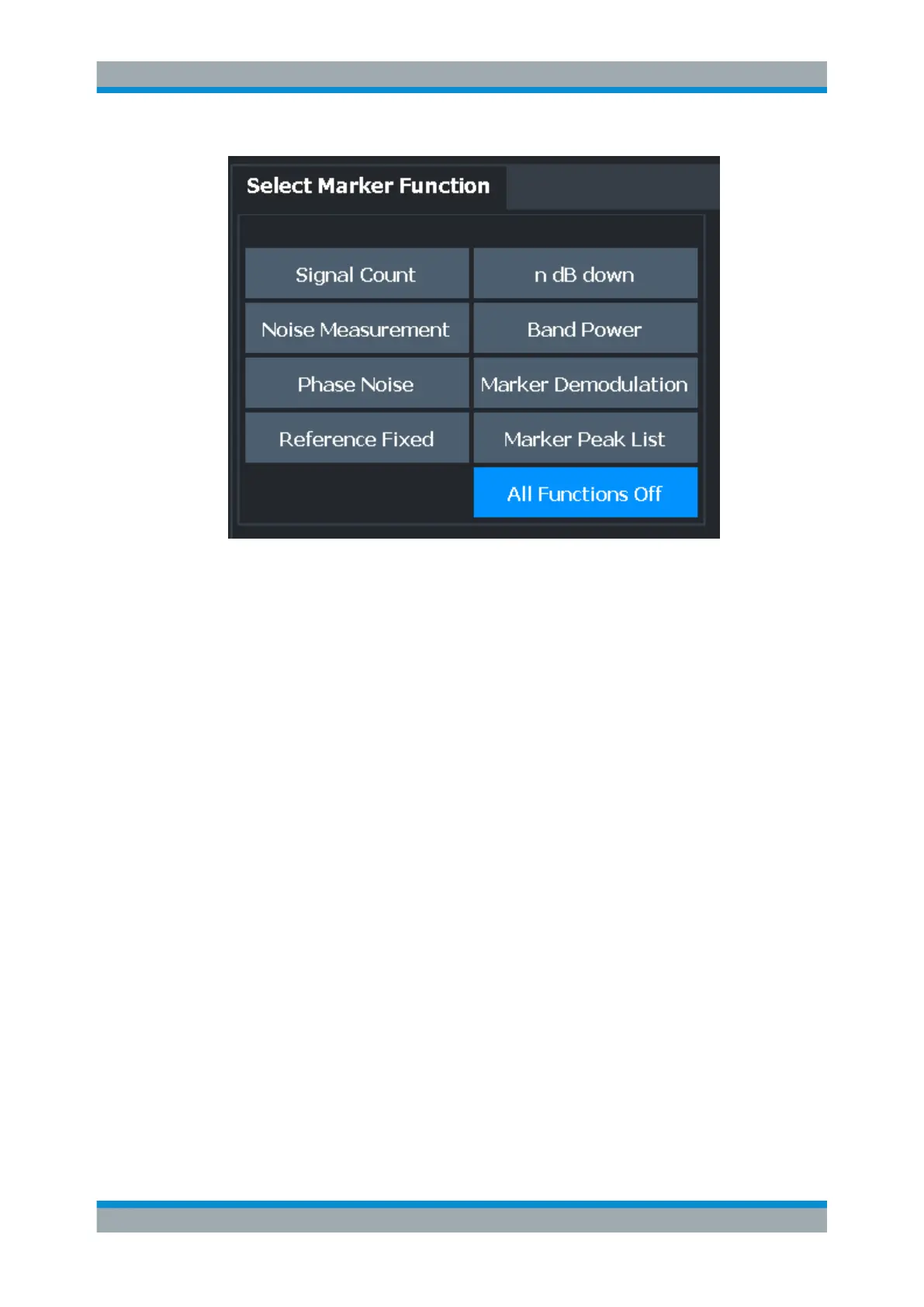
● Precise Frequency (Signal Count) Marker............................................................532
● Measuring Noise Density (Noise Meas Marker)....................................................534
● Phase Noise Measurement Marker.......................................................................537
● Measuring Characteristic Bandwidths (n dB Down Marker)..................................539
● Fixed Reference Marker........................................................................................541
● Measuring the Power in a Channel (Band Power Marker)....................................542
● Demodulating Marker Values and Providing Audio Output (Marker Demodulation)
.............................................................................................................................. 545
● Marker Peak List................................................................................................... 548
● Deactivating All Marker Functions.........................................................................551
9.3.4.1 Precise Frequency (Signal Count) Marker
Access: "Overview" > "Analysis" > "Marker Functions" > "Select Marker Function" >
"Signal Count" > "Signal Count Config"
Or: [MKR FUNC] > "Select Marker Function" > "Signal Count" > "Signal Count Config"
A normal marker determines the position of the point on the trace and indicates the sig-
nal frequency at this position. The trace, however, contains only a limited number of
points. Depending on the selected span, each trace point can contain many measure-
ment values. Thus, the frequency resolution of each trace point is limited.
(See also Chapter 8.5.1.8, "How Much Data is Measured: Sweep Points and Sweep
Count", on page 464).
Frequency resolution is further restricted by the RBW and sweep time settings.
Marker Usage

 Loading...


