Common Analysis and Display Functions
R&S
®
FSW
542User Manual 1173.9411.02 ─ 43
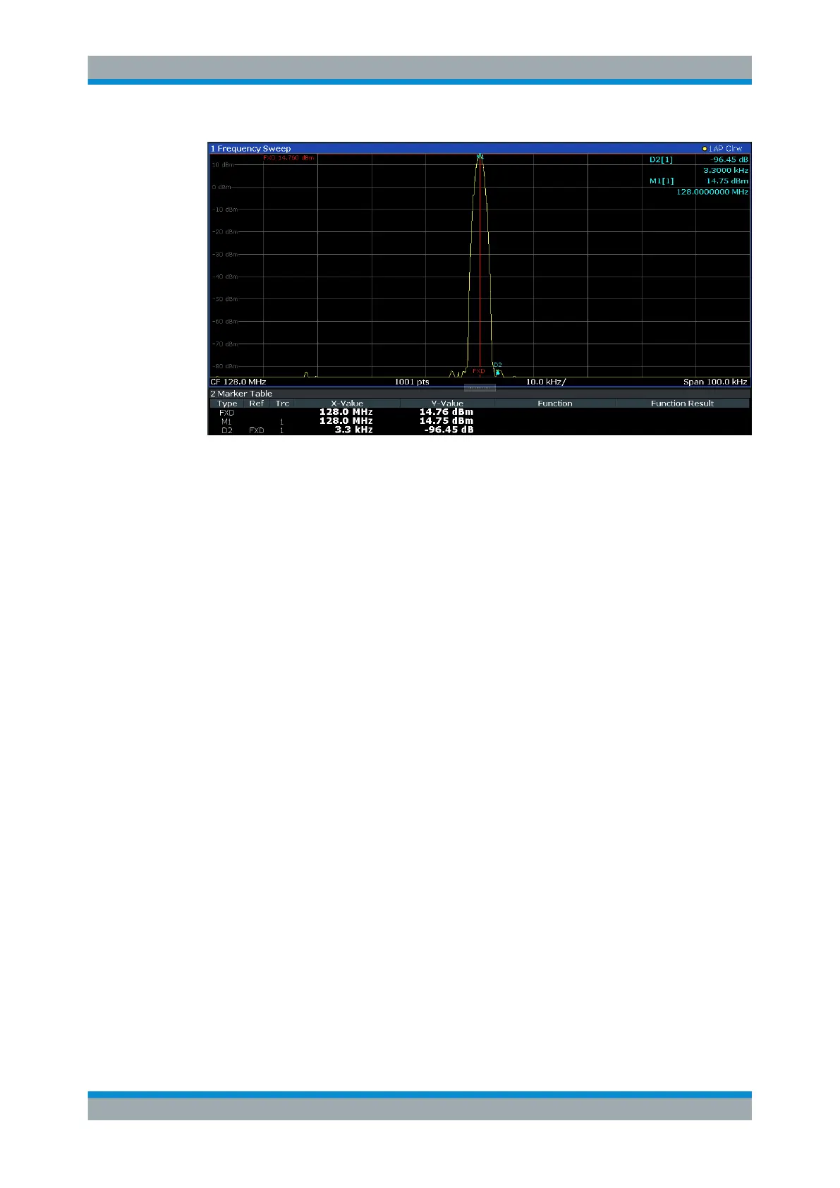
You can move the position of the fixed reference marker graphically by dragging the
display lines, or numerically by entering values for the marker position and level.
Remote commands:
"Example: Using a Fixed Reference Marker" on page 1203
CALCulate<n>:DELTamarker<m>:FUNCtion:FIXed[:STATe] on page 1180
CALCulate<n>:DELTamarker<m>:FUNCtion:FIXed:RPOint:X on page 1179
CALCulate<n>:DELTamarker<m>:FUNCtion:FIXed:RPOint:Y on page 1180
9.3.4.6 Measuring the Power in a Channel (Band Power Marker)
Access: "Overview" > "Analysis" > "Marker Functions" > "Band Power" > "Band Power
Config"
or: [MKR FUNC] > "Select Marker Function" > "Band Power"
To determine the noise power in a transmission channel, you could use a noise marker
and multiply the result with the channel bandwidth. However, the results would only be
accurate for flat noise.
Band power markers allow you to measure the integrated power for a defined span
(band) around a marker (similar to ACP measurements). By default, 5 % of the current
span is used. The span is indicated by limit lines in the diagram. The results can be
displayed either as a power (dBm) or density (dBm/Hz) value and are indicated in the
marker table for each band power marker.
Marker Usage

 Loading...


