Section 04 ENGINE (2-STROKE)
Subsection 05 (BOTTOM END)
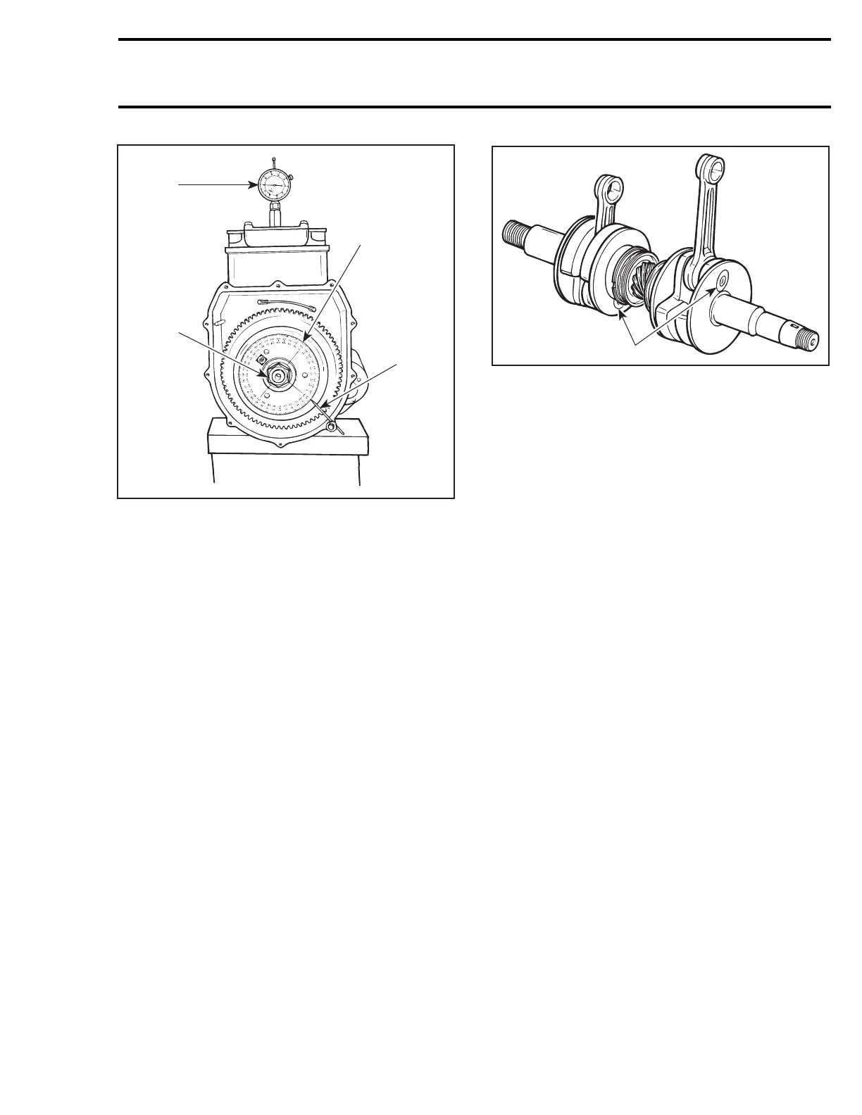
1
F01D4IA
3
2
4
TYPICAL
1. TDC gauge
2. Degree wheel
3. Hand tighten nut
4. Needle pointer
– Remove TDC gauge and install on PTO side.
– Bring PTO piston at Top Dead Center.
Interval between cylinders must be exactly 180°
therefore, needle pointer must indicate 180° on
degree wheel (360° -180°=180°).
Any other reading indicates a misaligned crank-
shaft.
CrankshaftAlignmentatConnecting
Rod Journal
Counterweights can also be twisted on connect-
ing rod journal on any or both cylinder(s).
F01D1NB
1
1. Connecting rod journal alignment here
Such misalignment may make it difficult to manu-
ally turn the crankshaft. Verification can be done
by measuring deflection each end of crankshaft.
If deflection is found greater than specified toler-
ance, this indicates worn bearing(s), bent and/or
disaligned crankshaft. Proceed with the disas-
sembly of the engine.
Disassembled Engine
The following verifications can be performed with
theenginedisassembled.
Crankcase
Inspect plane surfaces for warpage. Small defor-
mation can be corrected by grinding surface with
a fine sandpaper. Install sandpaper on a surface
plate and rub part against oiled sand paper.
Bearing
Inspect crankshaft bearings no. 4. Check for cor-
rosion, scoring, pitting, chipping or other evidence
of wear. Make sure plastic cage is not melted.
Rotate and make sure they turn smoothly.
Crankshaft
NOTE: If crankshaft and/or components are
found defective, it must be repaired by a special-
ized shop or replaced.
Connecting Rod Straightness
Align a steel ruler on edge of small end connecting
rod bore. Check if ruler is perfectly aligned with
edge of big end.
smr2004-Complete Line Up 141

 Loading...


