Section 05 ENGINE (4-TEC)
Subsection 02 (INTAKE SYSTEM)
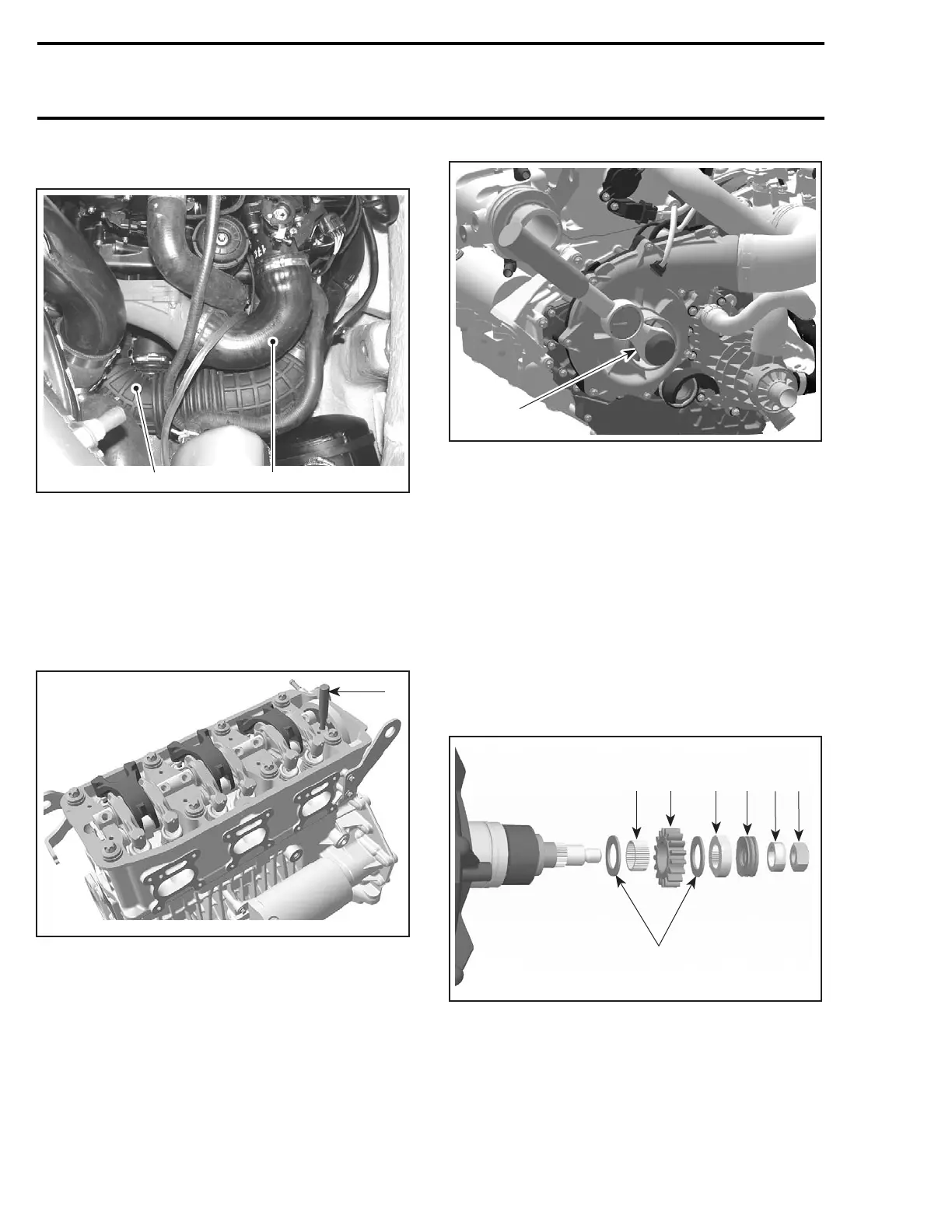
Remove air intake hose from supercharger ass'y.
1
R1503motr224A
2
1. Supercharger ass'y
2. Air intake hose
Remove valve cover and install camshaft locking
tool (P/N 529 035 839) to prevent camshaft ro-
tation while checking slipping moment of super-
charger. Refer to CYLINDER HEAD AND VALVES.
NOTE: Rotate supercharger nut to align camshaft
holes and to allow insertion of the locking tool.
R1503motr111A
1
1. Camshaft locking tool
Check slipping moment counterclockwise by us-
ing a torque wrench with actual torque viewe
r. A
mirror is useful to see the viewer.
1
R1503motr244A
1. Torque wrench
Supercharger should start to turn at a torque be-
tween7to12N•m (62 to 106 lbf•in).
If the torque is less, remove supercharger ass'y
from engine (refer to SUPERCHARGER RE-
MOVAL elsewhere in this section).
CAUTION: When removing the drive gear with
the needle pins, be careful not to lose one of
the40pins.
Loosen nut on supercharger shaft engine side.
Remove L-ring, spring washers, lock washer, ce-
ramic washers, drive gear and needle pins by turn-
ing the supercharger ass'y upside down.
1
R1503motr359A
234
5
67
1. Nut
2. L-Ring
3. Spring washers
4. Lock washer
5. Ceramic washers
6. Drive gear
7. Needle pins
190 smr2004-Complete Line Up

 Loading...


