Section 05 ENGINE (4-TEC)
Subsection 04 (REMOVAL AND INSTALLATION)
To verify alignment proceed as follows:
– Secure plate and support to hull with four nuts.
F19D0AA
– Install adapter (P/N 529 035 719 ) in engine PTO
housing.
1
F18D18A
1. Engine alignment adapter
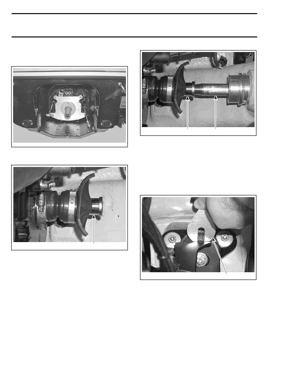
– Carefully slide shaft through support.
– Insert shaft end into engine alignment adapter.
NOTE: Ensure the protective hose and carbon ring
(or seal carrier) is removed to check engine align-
ment. If the alignment is correct, the shaft will
slide easily without any deflection in engine al
ign-
ment adapter.
1
F18D17A
2
TYPICAL
1. Engine alignment adapter
2. Alignment shaft
If the alignment is incorrect loosen engine sup-
port screws to enable to align engine alignment
adapter with shaft end.
NOTE: Use shim(s) (P/N 270 000 024) or (P/N 270
000 025) as necessary between engine supports
and rubber mounts to correct alignment.
1
F18D15A
TYPICAL
1. Shim
CAUTION: Whenever shims are used to cor-
rect alignment, never install more than 5 mm
(0.196 in) shim thickness.
Engine Support Screws
Apply Loctite 243 (blue) (P/N 293 800 060) on
screw threads.
Torque engine support screws to 25 N•m
(18 lbf•ft) when procedure is completed.
222 smr2004-Complete Line Up

 Loading...


