Section 05 ENGINE (4-TEC)
Subsection 07 (CYLINDER HEAD AND VALVES)
– chain guide no. 12
– Allen screws no. 13
– camshaft timing gear no. 14.
NOTE: Secure timing chain no. 15 with a retaining
wire.
Inspection
Check camshaft timing gear for wear or deteriora-
tion.
If gear is worn or damaged, replace it as a set
(camshaft timing gear and timing chain).
Forcrankshafttiminggear,refertoENGINE
BLOCK section.
Installation
For installation, reverse the removal procedure.
Pay attention to the following details.
Using the camshaft locking tool (P/N 529 035 839),
lock camshaft on TDC position.
1
R1503motr94A
2
1. Camshaft locking tool
2. Camshaft on TDC position
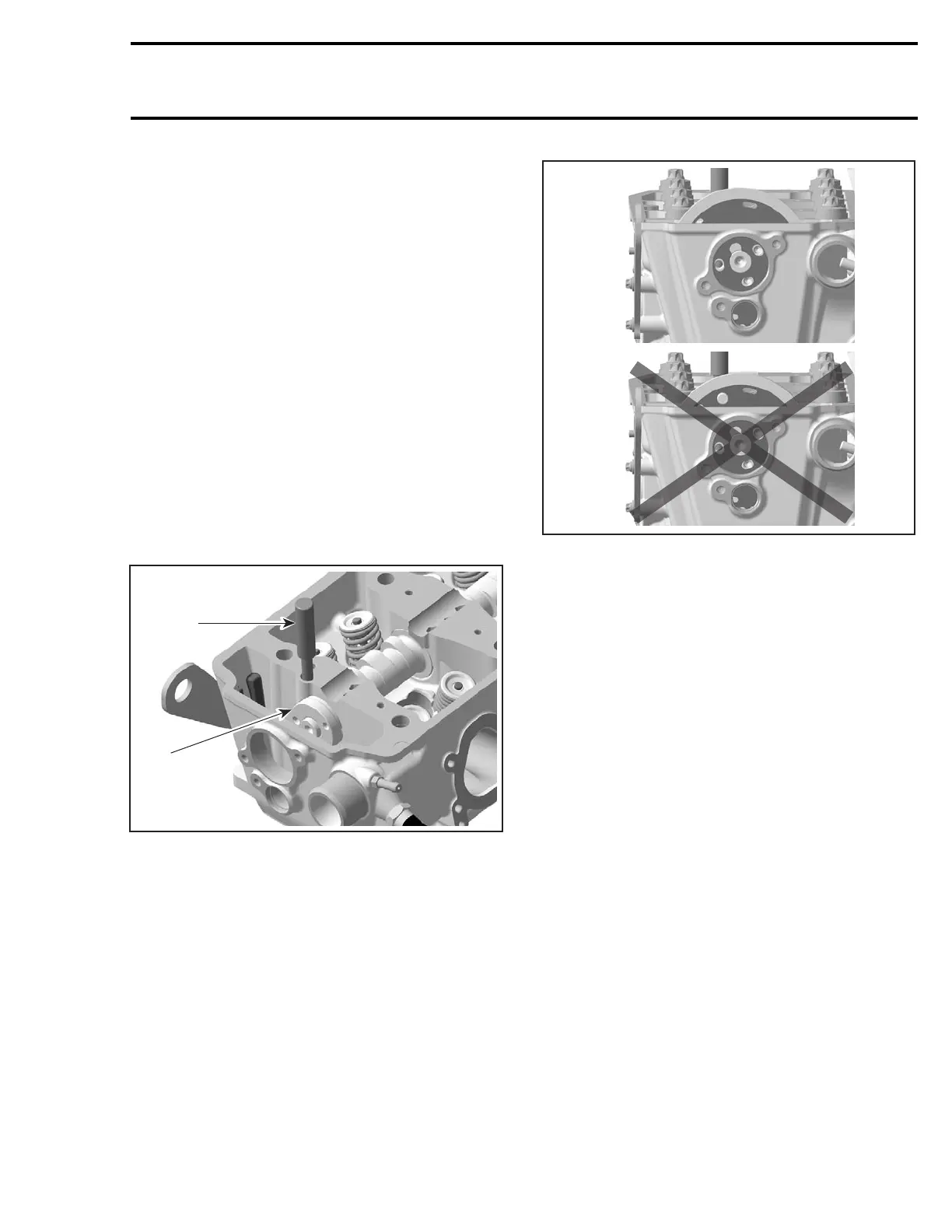
Install the camshaft timing gear with the writing
visible, i.e. to be able to see the position lines
when looking from outside of engine.
1
R1503motr97A
2
1. Good (with 1503 aligned)
2. Never
Install timing chain. Refer to ENGINE BLOCK sec-
tion.
Ensure chain guides are in place.
Loosely install screws.
Install chain tensioner.
NOTE: There can be 2 different positions to install
the timing gear on the camshaft. Basically both
positions are working well, since the camshaft and
crankshaft are locked in their proper position. Due
to some tolerances, there could be one position
which fits better than the other one. To check this,
perform the following test.
Check if screws are still loose. If screws are
squeezed by the timing gear, remove the chain
tensioner again and rotate timing gear by one
tooth clockwise. Then install the chain tensioner
again.
Tighten screws and torque to 10 N•m(89lbf•in).
Remove locking tools.
CAUTION: Crankshaft and camshaft must be
lockedonTDCpositiontoplacecamshafttim-
ing gear and timing chain in the proper posi-
tion. To double check, take a look at the timing
gear lines. They must be parallel to the cylin-
der head surface.
smr2004-Complete Line Up 261

 Loading...


