Section 08 ENGINE MANAGEMENT (4-TEC)
Subsection 02 (COMPONENT INSPECTION AND ADJUSTMENT)
NOTE: On the Supercharged Models ,amirror
is useful to see under throttle body.
To see the connector pin-out, temporarily remove
the connector shield joining the harness, to ex-
pose the terminal numbers. Connect a voltmeter
to the terminals of the wiring harness as per the
following table.
Remove and reinstall the safety lanyard to activate
the ECM.
Check the voltage readings as follows.
CONNECTION VOLTAGE
Terminal 1 with engine
ground
0V
Terminal 2 with engine
ground
5V
Terminal 3 with engine
ground
4.5 - 5 V
If voltage test is good, replace the TPS.
If voltage test is not good, check the resistance of
the TPS circuit.
Resistance Test
Reconnect the TPS.
Disconnect the ECM connector A on the ECM.
R1503motr191A
24
39
25
Using a multimeter, check resistance value be-
tween terminal A-25 and A-39.
The resistance shoul
d be 1600 - 2400
.
Check the resistance between terminal A-24 and
terminal A-39 with the throttle plate in idle posi-
tion.
The resistance should be approximately 2500
.
Check the resistance between terminal A-24 and
terminal A-39 with the throttle plate in wide open
position.
The resistance should be 1000 - 1100
.
Check the resistance between terminal A-24 and
A-25 with throttle plate in idle position.
The resistance should be 1000 - 1100
.
Now check the resistance with the throttle plate
in wide open position.
The resistance should be 2600 - 2700
.
NOTE: When measuring between terminals A-24
and A-39, resistance value decreases while
depressing throttle lever. when measuring be-
tween terminals A-24 and A-25, resistance value
increases while depressing throttle lever. The
resistance value should change smoothly and
proportionally to throttle movement. Otherwise,
replace TPS.
If resistance values are correct, try a new ECM.
Refer to ECM REPLACEMENT procedures else-
whereinthissection.
If resistance values are incorrect, repair connec-
tor or replace the wiring harness between ECM
connector and the TPS. If wiring harness and con-
nector test good, replace TPS.
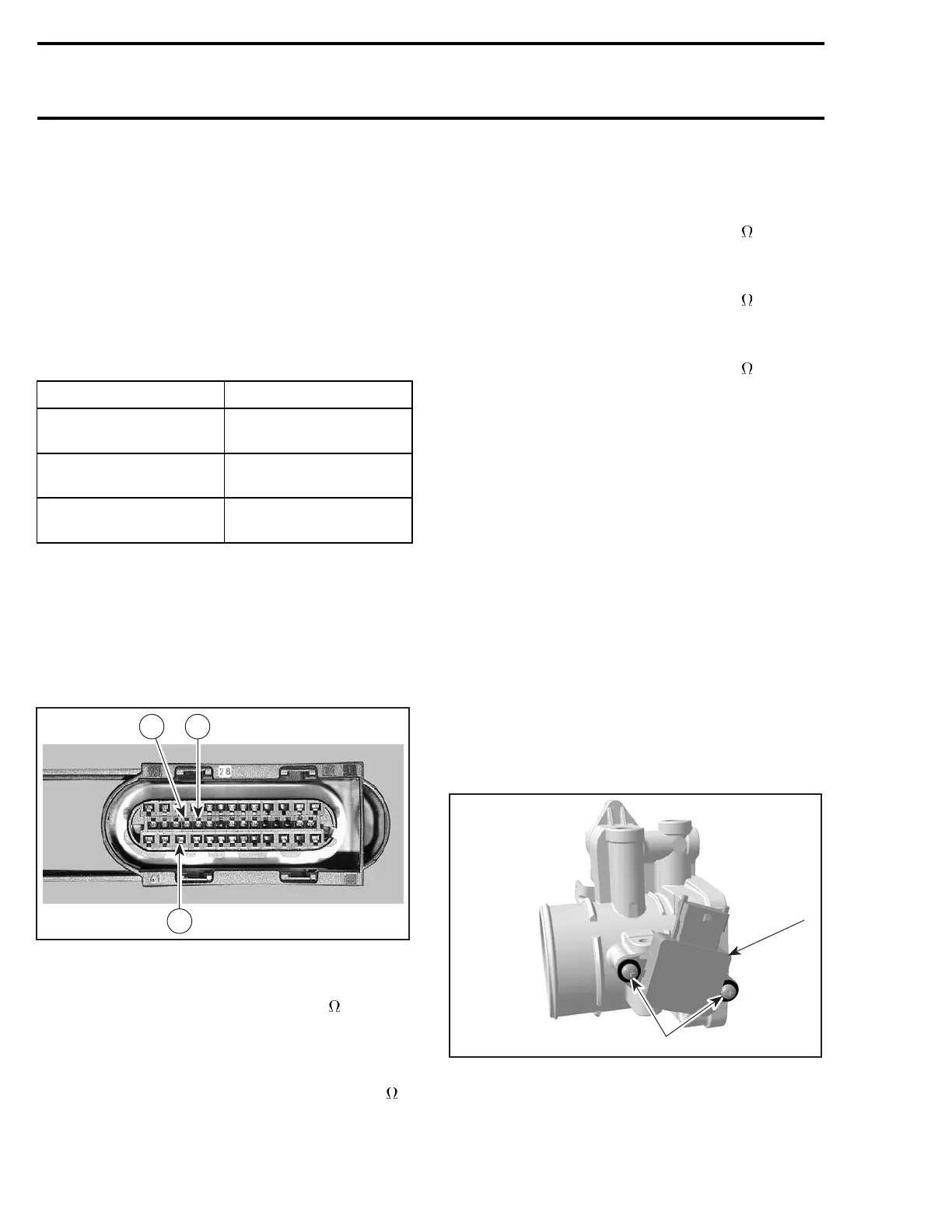
Replacement
Remove the throttle body as described above.
Loosen two screws retaining the TPS.
Remove TPS.
2
1
R1503motr168A
THROTTLE BODY
1. Throttle position sensor (TPS)
2. Screws
422 smr2004-Complete Line Up

 Loading...


