Section13PROPULSION
Subsection 02 (DRIVE SYSTEM)
Reinstall protective plate no. 18. Apply Loctite
243 (blue) on bolts and torque lock nuts to 10 N•m
(89 lbf•in).
Drive Shaft and Dampers
GTI Series
Install dampers no. 13 on drive shaft no. 12.
NOTE: Make sure dampers were not left in PTO
flywheel or impeller.
Install drive shaft and jet pump at the same time.
Insert drive shaft through carbon ring no. 8 and
floating ring no. 6.
NOTE: Make sure to install floating ring before
inserting the drive shaft in the PTO flywheel.
While holding jet pump, guide and engage drive
shaft splines in PTO flywheel. Rotate shaft to
properly index splines. Make sure boot is well po-
sitioned over shaft end.
Circlip
All Models except 4-TEC Models
Push the floating ring to compress the boot. In-
sert the circlip no. 5 in the drive shaft groove.
F06I06A
1 2
1. Push floating ring
2. Insert circlip in the groove
Slide the floating ring onto the circlip.
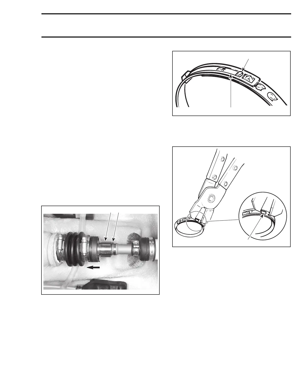
Large Clamp
GTI Series
Secure large clamp no. 2 as follows:
– Use pliers (P/N 295 000 069) as for removal.
– Manually engage holding hook in large window.
This is a pre-clamping position only.
F01J23A
1
2
PRE-CLAMPING POSITION
1. Holding hook
2. Large window
– Insert pointed tips of pliers first in closing hooks.
1
F01J2BA
TYPICAL
1. Closing hooks
– Squeeze pliers. When both large and small
windows are directly over the 2 locking hooks,
press those windows down to engage hooks
in windows.
NOTE: At installation, clamp tail should be in op-
posite direction of engine rotation.
smr2004-Complete Line Up 669

 Loading...


