Issue 01/06 Parameter Description
MICROMASTER 440 Parameter List
6SE6400-5BB00-0BP0
149
Caution:
If P1245 increased too much, it may interfere with the drive normal operation.
Note:
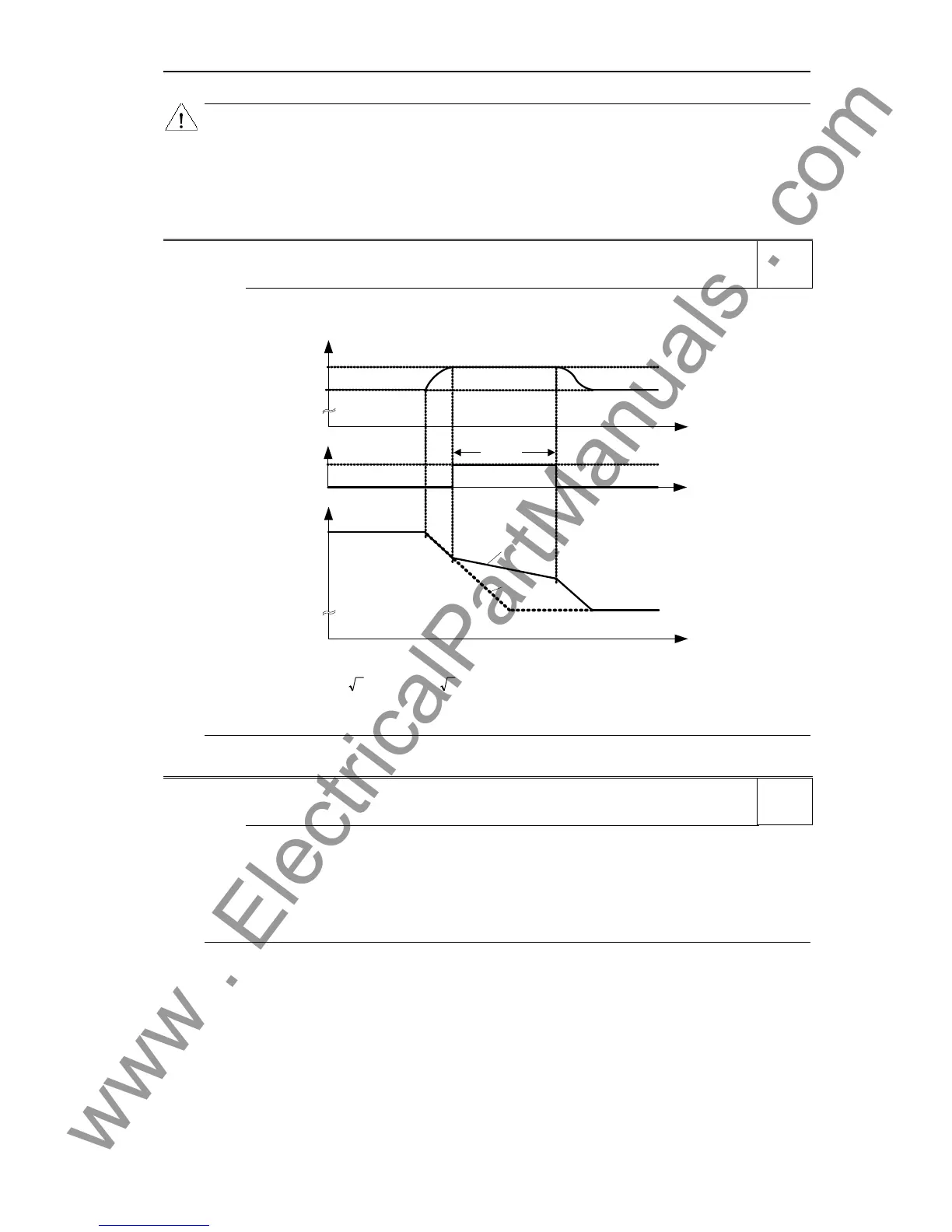
Vdc max controller automatically increases ramp-down times to keep the DC-link voltage (r0026) within
limits (r1242).
Vdc min is activated if DC-link voltage falls below the switch on level,P1245. The kinetic energy of the motor
is then used to buffer the DC-link voltage, thus causing deceleration of the drive. If the drive trips F0003
immediately, try increasing the dynamic factor first, P1247. If still tripping F0003 try then increasing the
switch on level, P1245.
r1242 CO: Switch-on level of Vdc-max Min: -
Datatype: Float Unit: V Def: -
P-Group: FUNC Max: -
Displays switch-on level of Vdc max controller.
t
t
f
1
-controller activeV
DC_max
t
V
DC
r1242
0
r0056 Bit14
f
f
act
set
A0911
Following equation is only valid , if P1254 = 0 :
0210P215.1V21.15 = r1242
mains
⋅⋅⋅⋅
=
otherwise :
r1242 is internally calculated
Note:
Parameter r1242 (switch-in threshold) is determined by each power cycle, when precharging of the DC-link
is finished.
P1243[3] Dynamic factor of Vdc-max Min: 10
CStat: CUT Datatype: U16 Unit: % Def: 100
P-Group: FUNC Active: Immediately QuickComm.: No Max: 200
Defines dynamic factor for DC link controller in [%].
Index:
P1243[0] : 1st. Drive data set (DDS)
P1243[1] : 2nd. Drive data set (DDS)
P1243[2] : 3rd. Drive data set (DDS)
Dependency:
P1243 = 100 % means parameters P1250, P1251 and P1252 (gain, integration time and differential time)
are used as set. Otherwise, these are multiplied by P1243 (dynamic factor of Vdc-max).
Note:
Vdc controller adjustment is calculated automatically from motor and inverter data.
Level
3
Level
3

 Loading...


