Issue 01/06 Parameter Description
MICROMASTER 440 Parameter List
6SE6400-5BB00-0BP0
179
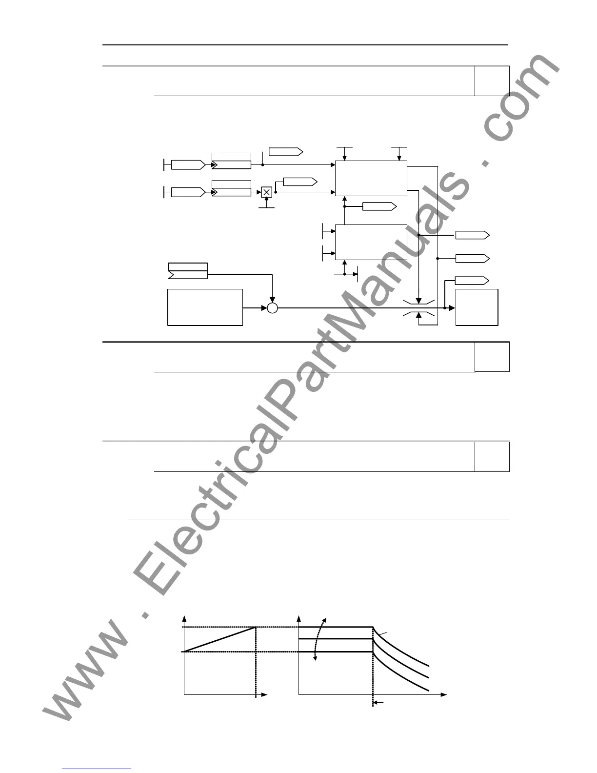
r1538 CO: Upper torque limit (total) Min: -
Datatype: Float Unit: Nm Def: -
P-Group: CONTROL Max: -
Displays total upper torque limitation.
P1530
Motoring power lim
Current
controller
Speed controller
or
Torque controller
CO: Lower trq. lim
r1538
CO:Total up TrqLim [Nm]
r0079
CO: Total trq setp [Nm ]
r0067
CO: Outp cur limit [A]
CI: Add. trq. setp
(0:0)
P1511.C
Torque limitation
Torque limitation :
P15 21
P15 20
CI: Upper trq. lim
(1520:0)
P1522.C
CI: Lower trq. lim
(1521:0)
P1523.C
P0640
Motor ovl fact [%]
Motor / inverter
protection
P0305
Rated mot. current
Max. inverter cur [ A]
r0209
CO: Upper trq. lim
P15 25
Scal. low trq . lim
P1531
Regener. power lim
r1539
CO:Total lw TrqLim [Nm]
r1526
CO: Upper trq. lim [Nm]
r1527
CO: Lower trq. lim [Nm]
r1539 CO: Lower torque limit (total) Min: -
Datatype: Float Unit: Nm Def: -
P-Group: CONTROL Max: -
Displays total lower torque limitation.
Details:
See parameter r1538.
3.29.2.7 Flux control
P1570[3] CO: Fixed value flux setpoint Min: 50.0
CStat: CUT Datatype: Float Unit: % Def: 107.0
P-Group: CONTROL Active: Immediately QuickComm.: No Max: 200.0
Parameter to set the flux setpoint as a % relative to the rated motor flux.
Index:
P1570[0] : 1st. Drive data set (DDS)
P1570[1] : 2nd. Drive data set (DDS)
P1570[2] : 3rd. Drive data set (DDS)
Note:
- In the base speed range, the flux setpoint P1570 is converted into the field-generating current
component isd (P1570 = 100% corresponds to r0331).
- For values below 100%, the drive is under-magnetized and above this, is over-magnetized.
- If P1570 is set to more than 100%, then the flux setpoint, depending on the load, is increased from
100% (under no-load conditions) to this value (under rated load, refer to the diagram).
- If in so doing, the maximum drive inverter output voltage is reached, the rotor flux is reduced in order to
keep the output voltage constant (or the EMF) with increasing speed.
- The maximum possible output voltage r0071 of the drive inverter is determined by the DC link voltage
r0026 and the maximum modulation depth P1803 in the gating unit.
P1570
i
N,Motor
i
Motor
Ψ
Ψ
N
set
(100 %)
Field weakening
f
Ψ
i
N,Motor
i
Motor
Level
2
Level
2
Level
2

 Loading...


