Parameter Description Issue 01/06
MICROMASTER 440 Parameter List
216 6SE6400-5BB00-0BP0
P2172[3] Threshold DC-link voltage Min: 0
CStat: CUT Datatype: U16 Unit: V Def: 800
P-Group: ALARMS Active: Immediately QuickComm.: No Max: 2000
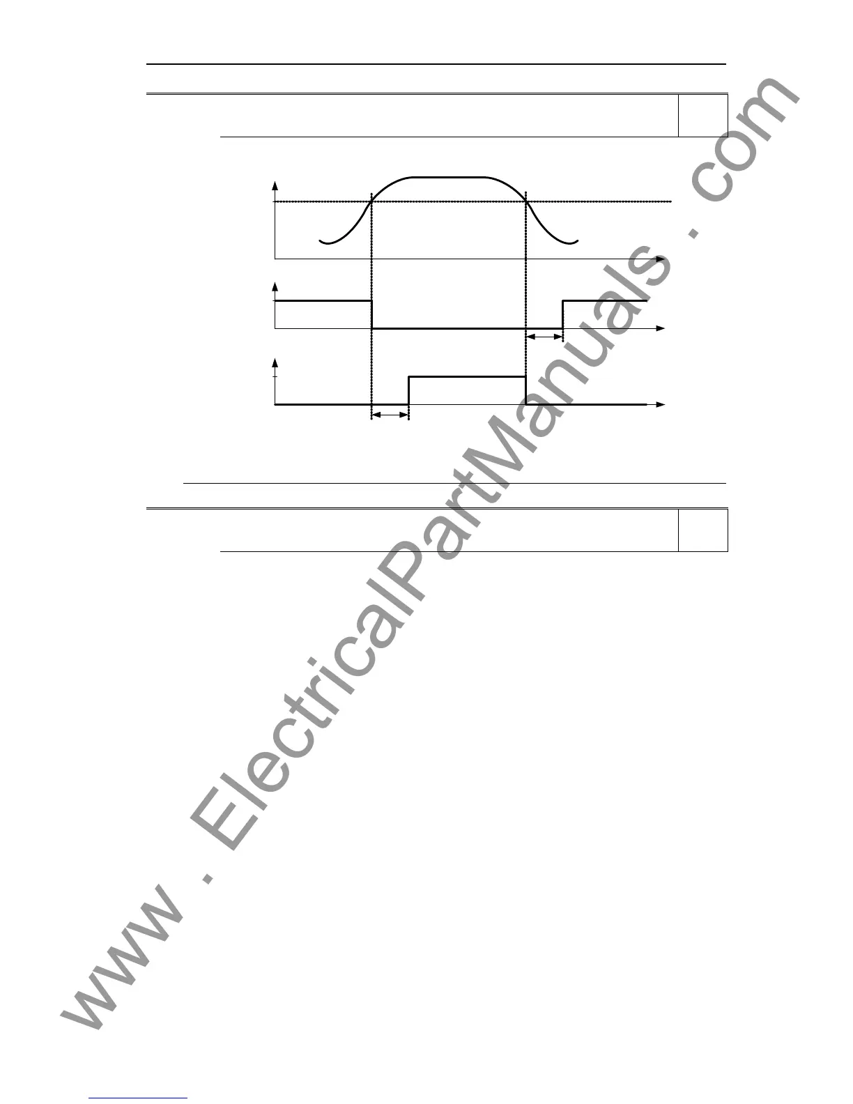
Defines DC link voltage to be compared to actual voltage as illustrated in the diagram below.
V
dc
t
0
1
0
1
P2173
t
t
r0053
Bit07
r0053
Bit08
P2172
P2173
V
dc_act
< P2172
V
dc_act
> P2172
Index:
P2172[0] : 1st. Drive data set (DDS)
P2172[1] : 2nd. Drive data set (DDS)
P2172[2] : 3rd. Drive data set (DDS)
Note:
This voltage controls bits 7 and 8 in status word 3 (r0053).
P2173[3] Delay time DC-link voltage Min: 0
CStat: CUT Datatype: U16 Unit: ms Def: 10
P-Group: ALARMS Active: Immediately QuickComm.: No Max: 10000
Defines delay time prior to activation of threshold comparison.
Index:
P2173[0] : 1st. Drive data set (DDS)
P2173[1] : 2nd. Drive data set (DDS)
P2173[2] : 3rd. Drive data set (DDS)
Details:
See diagram in P2172 (threshold DC-link voltage)
Level
3
Level
3

 Loading...


