Parameter Description Issue 01/06
MICROMASTER 440 Parameter List
26 6SE6400-5BB00-0BP0
Dependency:
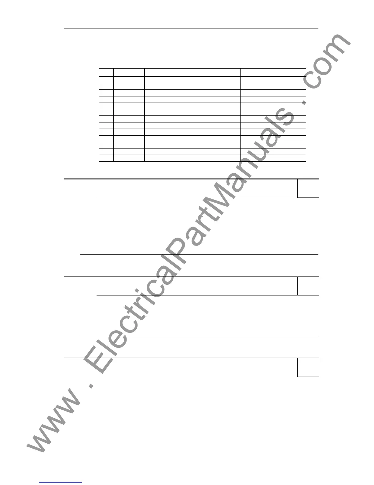
The parameters are sub-divided into groups (P-Group) according to their functionality. This increases the
transparency and allows a parameter to be quickly searched for. Furthermore, parameter P0004 can be
used to control the ability to be visualized for the operator panel.
ALWAYS
INVERTER
MOTOR
ENCODER
TECH_APL
COMMANDS
TERMINAL
SETPOINT
FUNC
CONTROL
COMM
ALARMS
TECH Technological controller (PID controller)
0200 .... 0299
Parameter area
0300 ... 0399 + 0600 .... 0699
0400 .... 0499
0500 .... 0599
0700 .... 0749 + 0800 ... 0899
0750 .... 0799
1000 .... 1199
1200 .... 1299
1300 .... 1799
2000 .... 2099
2100 .... 2199
2200 .... 2399
Value
0
2
3
4
5
7
8
10
12
13
20
21
22
Group
All parameters
Drive inverter parameters
Motor parameters
Speed encoder
Technical applications / units
Control commands, digital I/O
Analog inputs/outputs
Setpoint channel and ramp-function gen.
Drive inverter functions
Motor open-loop/closed-loop control
Communications
Faults, warnings, monitoring functions
P-Group
Parameters marked "Quick Comm: Yes" in the parameter header can only be set when P0010 = 1 (Quick
Commissioning).
P0005[3] Display selection Min: 2
CStat: CUT Datatype: U16 Unit: - Def: 21
P-Group: FUNC Active: first confirm QuickComm.: No Max: 4000
Selects display for parameter r0000 (drive display).
Index:
P0005[0] : 1st. Drive data set (DDS)
P0005[1] : 2nd. Drive data set (DDS)
P0005[2] : 3rd. Drive data set (DDS)
Common Settings:
21 Actual frequency
25 Output voltage
26 DC link voltage
27 Output current
Notice:
These settings refer to read only parameter numbers ("rxxxx").
Details:
See relevant "rxxxx" parameter descriptions.
P0006 Display mode Min: 0
CStat: CUT Datatype: U16 Unit: - Def: 2
P-Group: FUNC Active: first confirm QuickComm.: No Max: 4
Defines mode of display for r0000 (drive display).
Possible Settings:
0 In Ready state alternate between setpoint and output frequency. In run display output frequency
1 In Ready state display setpoint. In run display output frequency.
2 In Ready state alternate between P0005 value and r0020 value. In run display P0005 value
3 In Ready state alternate between r0002 value and r0020 value. In run display r0002 value
4 In all states just display P0005
Note:
- When inverter is not running, the display alternates between the values for "Not Running" and
"Running".
- Per default, the setpoint and actual frequency values are displayed alternately.
P0007 Backlight delay time Min: 0
CStat: CUT Datatype: U16 Unit: - Def: 0
P-Group: FUNC Active: first confirm QuickComm.: No Max: 2000
Defines time period after which the backlight display turns off if no operator keys have been pressed.
Value:
P0007 = 0:
Backlight always on (default state).
P0007 = 1 - 2000:
Number of seconds after which the backlight will turn off.
Level
2
Level
3
Level
3

 Loading...


