Issue 01/06 Parameter Description
MICROMASTER 440 Parameter List
6SE6400-5BB00-0BP0
89
ADC1
ADC2
OFF = [V], 0 - 10 V
ON = [A], 0 - 20 mA
1234 5
6
789
OFF = [V], 0 - 10 V
ON = [A], 0 - 20 mA
Possible Settings:
0 Unipolar voltage input (0 to +10 V)
1 Unipolar voltage input with monitoring (0 to 10 V)
2 Unipolar current input (0 to 20 mA)
3 Unipolar current input with monitoring (0 to 20 mA)
4 Bipolar voltage input (-10 V to +10 V)
Index:
P0756[0] : Analog input 1 (ADC 1)
P0756[1] : Analog input 2 (ADC 2)
Notice:
When monitoring is enabled and a deadband defined (P0761), a fault condition will be generated (F0080) if
the analog input voltage falls below 50 % of the deadband voltage.
On account of h/w restirction it is not possible to select the bipolar voltage (see Enum declaration) for
analog input 2 (P0756[1] = 4).
Details:
See P0757 to P0760 (ADC scaling).
P0757[2] Value x1 of ADC scaling [V / mA] Min: -20
CStat: CUT Datatype: Float Unit: - Def: 0
P-Group: TERMINAL Active: first confirm QuickComm.: No Max: 20
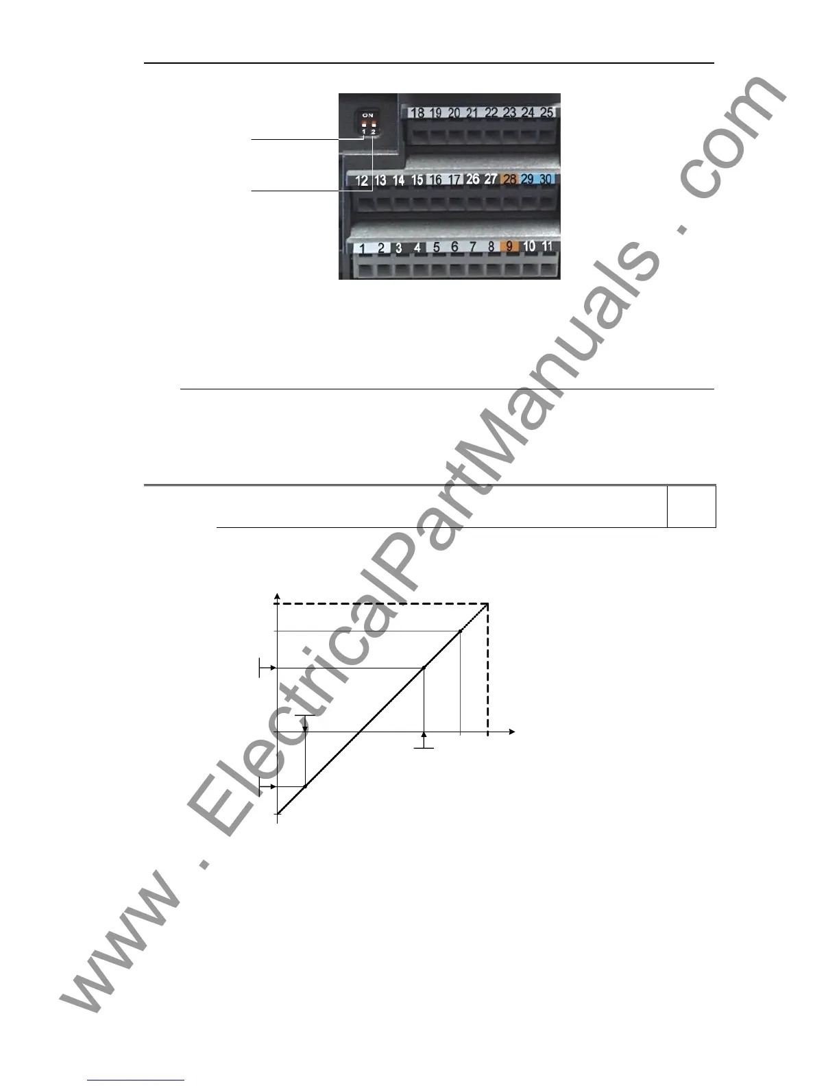
Parameters P0757 - P0760 configure the input scaling as shown in the diagram:
ASPmax
100 %
10 V
20 mA
V
mA
x
100%
%
P0760
P0758
P0757
P0759
P0756 = 0 ... 3, P0761 = 0
ASPmin
4000 h
Where:
- Analog setpoints represent a [%] of the normalized frequency in P2000.
- Analog setpoints may be larger than 100 %.
- ASPmax represents highest analog setpoint (this may be at 10 V or 20 mA).
- ASPmin represents lowest analog setpoint (this may be at 0 V or 20 mA).
- Default values provide a scaling of 0 V or 0 mA = 0 %, and 10 V or 20 mA = 100 %.
Level
2

 Loading...


