Parameter Description Issue 01/06
MICROMASTER 440 Parameter List
86 6SE6400-5BB00-0BP0
r0747 CO/BO: State of digital outputs Min: -
Datatype: U16 Unit: - Def: -
P-Group: COMMANDS Max: -
Displays status of digital outputs (also includes inversion of digital outputs via P0748).
Bitfields:
Bit00 Digital output 1 energized 0 NO 1 YES
Bit01 Digital output 2 energized 0 NO 1 YES
Bit02 Digital output 3 energized 0 NO 1 YES
Dependency:
Bit 0 = 0 :
Relay de-energized / contacts open
Bit 0 = 1 :
Relay energized / contacts closed
P0748 Invert digital outputs Min: 0
CStat: CUT Datatype: U16 Unit: - Def: 0
P-Group: COMMANDS Active: first confirm QuickComm.: No Max: 7
Defines high and low states of relay for a given function.
Bitfields:
Bit00 Invert digital output 1 0 NO 1 YES
Bit01 Invert digital output 2 0 NO 1 YES
Bit02 Invert digital output 3 0 NO 1 YES
3.11 Analog inputs
r0750 Number of ADCs Min: -
Datatype: U16 Unit: - Def: -
P-Group: TERMINAL Max: -
Displays number of analog inputs available.
r0751 BO: Status word of ADC Min: -
Datatype: U16 Unit: - Def: -
P-Group: TERMINAL Max: -
Displays status of analog input.
Bitfields:
Bit00 Signal lost on ADC 1 0 NO 1 YES
Bit01 Signal lost on ADC 2 0 NO 1 YES
Dependency:
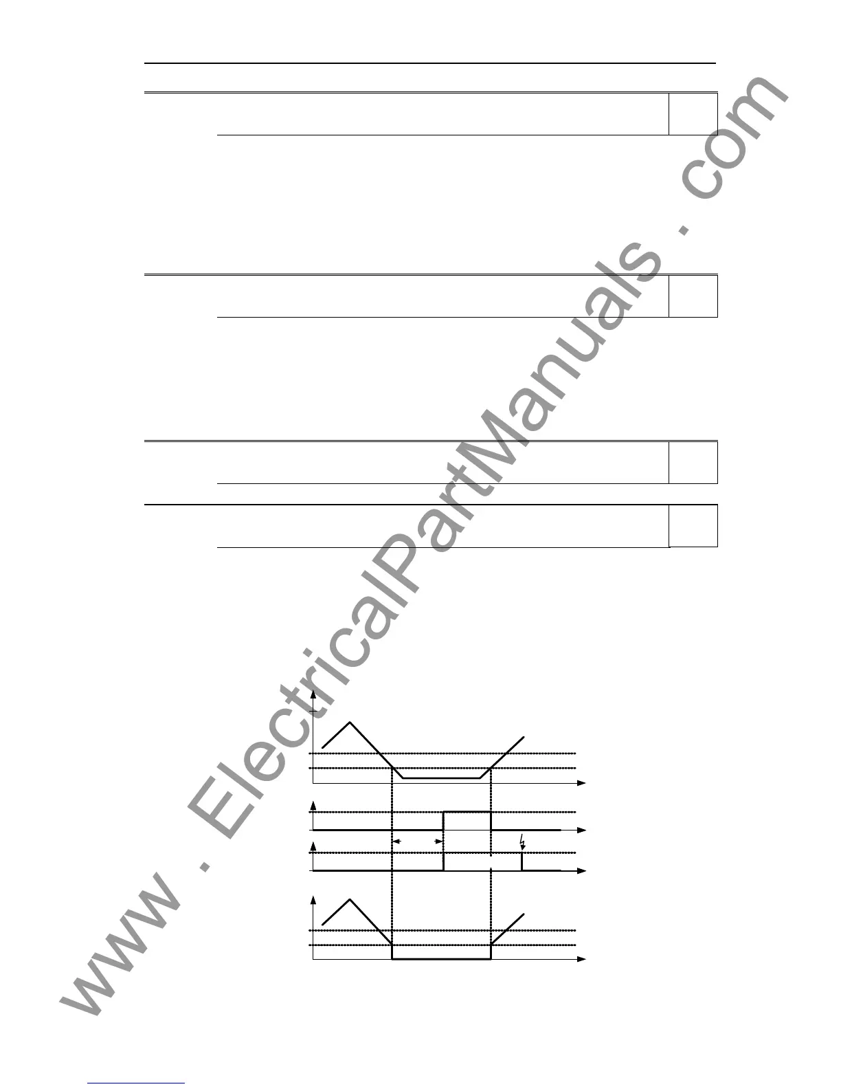
The following limitations/secondary conditions apply for the wire breakage monitoring:
- For P0756, the monitoring must be activated
- Width of the ADC deadzone P0761 > 0
- Wire breakage / signal loss F0080 is detected if the ADC input quantity is less than 0.5 * P0761.
t0
Signal loss
t0
P0761
V
1
P0761 0,5⋅
10
P0762
r0751
t0
1
F0080
Fault acknowl.
Analog input
t0
Act. ADC after scaling
r0755
Level
3
Level
3
Level
3
Level
4

 Loading...


