Function Diagrams Issue 01/06
MICROMASTER 440 Parameter List
284 6SE6400-5BB00-0BP0
- 4180 -
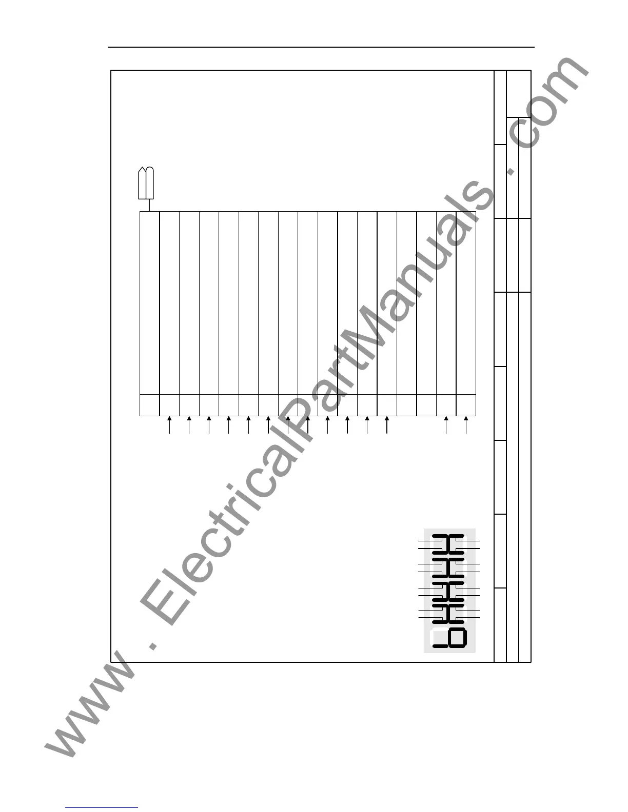
Function diagram
87654321
4180_ZSW2.vsd
Technology Functions
MICROMASTER 440
16.01.2006 V2.1
Status word 2 (r0053)
1)
The sequence control is the internal
control (software) for realizing the drive
status (r0002)
CO/BO: Act StatWd2
r0053
r0053
1 03 25 47 6
9 8
11 1013 1215 14
Segment Bit
Segment Bit
Seven-segment display
Braking control
Messages
Alarm processing
Messages
Sequence control 1)
Alarm processing
Messages
Alarm processing
Messages
Sequence control 1)
Messages
Messages
Messages
Sequence control 1)
1
2
3
4
5
6
7
8
9
10
11
12
13
14
15
0
Bit No. Meaning
1 = DC brake active
0 = DC brake not active
1 = f_act > P2167 (f_off)
1 = f_act >= P1080 (f_min)
Parameter r0053
1 = Act. current r0027 >= P2170
1 = f_act > P2155 (f_1)
1 = f_act <= P2155 (f_1)
1 = f_act >= setpoint
1 = Act. Vdc r0026 < P2172
1 = Act. Vdc r0026 > P2172
1 = Ramping finished
1 = PID output r2294 == P2292 (PID_min)
1 = PID output r2294 == P2291 (PID_max)
reserved
Download data set 0 from AOP
Download data set 1 from AOP
reserved
reserved

 Loading...


