Issue 01/06 Function Diagrams
MICROMASTER 440 Parameter List
6SE6400-5BB00-0BP0
271
- 2700 -
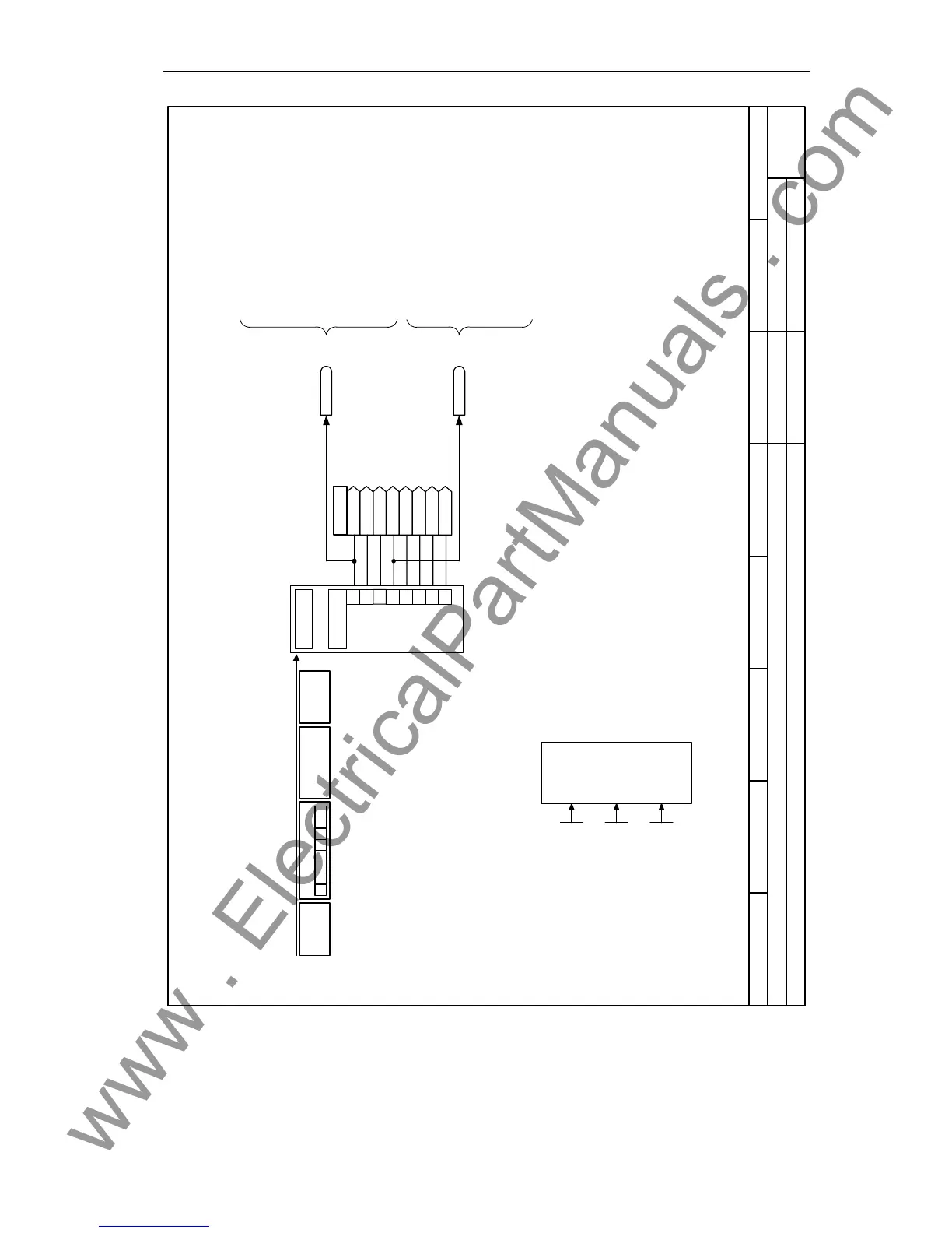
Function diagram
87654321
2700_CBonCOM.vsd
External Interfaces
MICROMASTER 440
16.01.2006 V2.1
CB on COM link, Receiving
PKW
PZD
1
[0]
r2050
[1]
[2]
[3]
2
3
4
5
6
7
[4]
[5]
[6]
[7]
CB tel. off time
0 ... 65535 [ms]
P2040 (20)
BO: CtrlWd1 <- CB
r2090
BO: CtrlWd2 <- CB
r2091
PZD
PKW
7 6 5 4 3 2 1
Receive telegram
RxD
Receive
CB
configuration
Change par. via
0 ... 15
P0927 (15)
CB parameter
0 ... 65535
P2041 [5] (0)
Bit0 = 1
Note:
Bit 10 must be set in the first PZD word of the
telegram received via USS so that the converter
will accept the process data as
being valid. For this reason, the control
word 1 must be transferred to the converter
in the first PZD word.
Bit00 ON/OFF1
Bit01 OFF2: Electrical stop
Bit02 OFF3: Fast stop
Bit03 Pulse enable
Bit04 RFG enable
Bit05 RFG start
Bit06 Setpoint enable
Bit07 Fault acknowledge
Bit08 JOG right
Bit09 JOG left
Bit10 Control from PLC
Bit11 Reverse (setpoint inversion)
Bit13 Motor potentiometer MOP up
Bit14 Motor potentiometer MOP down
Bit15 CDS Bit 0 (Local/Remote)
Bit00 Fixed frequency Bit 0
Bit01 Fixed frequency Bit 1
Bit02 Fixed frequency Bit 2
Bit03 Fixed frequency Bit 3
Bit04 Drive data set (DDS) Bit 0
Bit05 Drive data set (DDS) Bit 1
Bit08 PID enabled
Bit09 DC brake enabled
Bit11 Droop
Bit12 Torque control
Bit13 External fault 1
Bit15 Command data set (CDS) Bit 1
CB-Frame
CB-Frame
0
0

 Loading...


