Issue 01/06 Parameter Description
MICROMASTER 440 Parameter List
6SE6400-5BB00-0BP0
91
P0759[2] Value x2 of ADC scaling [V / mA] Min: -20
CStat: CUT Datatype: Float Unit: - Def: 10
P-Group: TERMINAL Active: first confirm QuickComm.: No Max: 20
Sets value of X2 as described in P0757 (ADC scaling).
Index:
P0759[0] : Analog input 1 (ADC 1)
P0759[1] : Analog input 2 (ADC 2)
Notice:
The value x2 of ADC scaling P0759 must be greater than the value x1 of ADC scaling P0757.
P0760[2] Value y2 of ADC scaling Min: -99999.9
CStat: CUT Datatype: Float Unit: % Def: 100.0
P-Group: TERMINAL Active: first confirm QuickComm.: No Max: 99999.9
Sets value of Y2 in [%] as described in P0757 (ADC scaling).
Index:
P0760[0] : Analog input 1 (ADC 1)
P0760[1] : Analog input 2 (ADC 2)
Dependency:
Affects P2000 to P2003 (reference frequency, voltage, current or torque) depending on which setpoint is to
be generated.
P0761[2] Width of ADC deadband [V / mA] Min: 0
CStat: CUT Datatype: Float Unit: - Def: 0
P-Group: TERMINAL Active: first confirm QuickComm.: No Max: 20
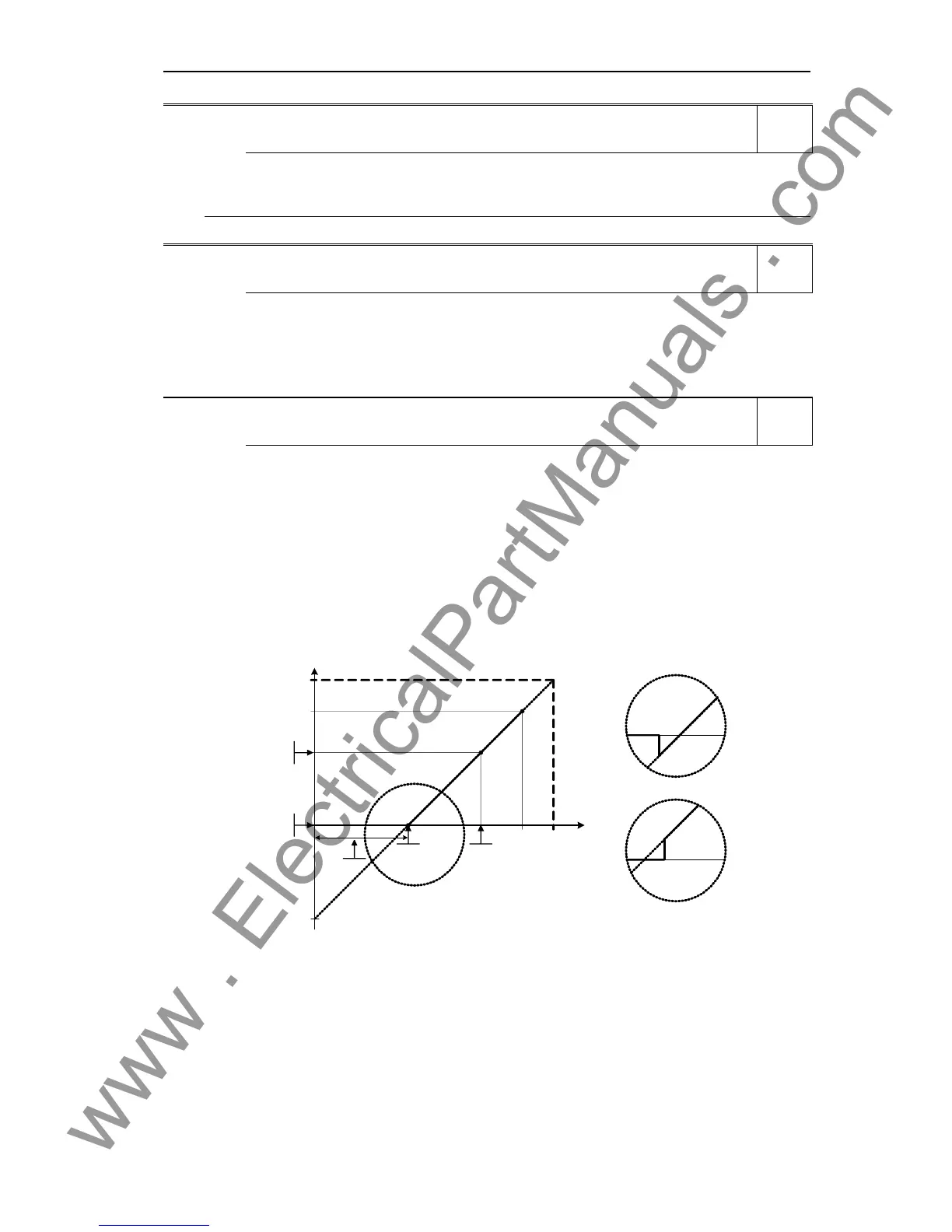
Defines width of deadband on analog input. The diagrams below explain its use.
Index:
P0761[0] : Analog input 1 (ADC 1)
P0761[1] : Analog input 2 (ADC 2)
Example:
The below example produces a 2 to 10 V analog input 0 to 50 Hz (ADC value 2 to 10 V, 0 to 50 Hz):
- P2000 = 50 Hz
- P0759 = 8 V P0760 = 75 %
- P0757 = 2 V P0758 = 0 %
- P0761 = 2 V
- P0756 = 0 or 1
ASPmax
100 %
10 V
20 mA
V
mA
x
100%
%
P0760
P0758
P0759
ASPmin
P0757
P0761
P0757 = P0761
P0757 > P0761
P0757 < P0761
4000 h
P0761 > 0 and (0 < P0758 < P0760 or 0 > P0758 > P0760)
The below example produces a 0 to 10 V analog input (-50 to +50 Hz) with center zero and a "holding point"
0.2 V wide (0.1 V to each side of center, ADC value 0 to 10 V, -50 to +50 Hz):
- P2000 = 50 Hz
- P0759 = 8 V P0760 = 75 %
- P0757 = 2 V P0758 = -75 %
- P0761 = 0.1 V
- P0756 = 0 or 1
Level
2
Level
2
Level
2

 Loading...


