Parameter Description Issue 01/06
MICROMASTER 440 Parameter List
222 6SE6400-5BB00-0BP0
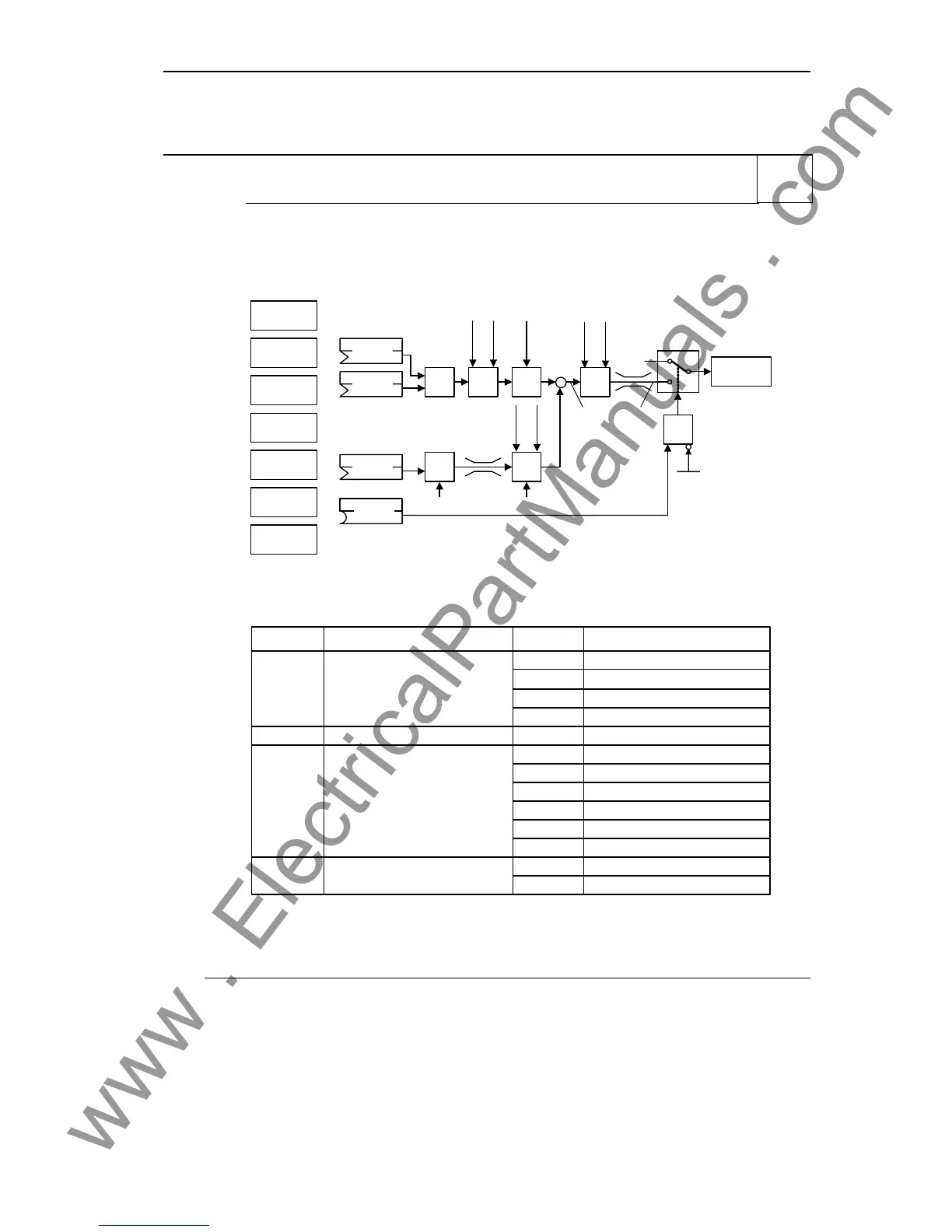
3.37 Technology controller (PID controller)
P2200[3] BI: Enable PID controller Min: 0:0
CStat: CUT Datatype: U32 Unit: - Def: 0:0
P-Group: TECH Active: first confirm QuickComm.: No Max: 4000:0
Allows user to enable/disable the PID controller.
: PID controller de-activated
: PID controller permanently activated
: PID controller event-controlled, de-activated/activated
0
1
BICO parameters
P2200 settings :
PID
MOP
ADC
PID
SUM
PID
PID
FF
USS
BOP link
USS
COM link
CB
COM link
ADC2
P2254
P2253
PID
RFG
PID
PT1
−
∆
PID
P2200
P2264
PID
PT1
PID
SCL
&
P2251
Output
PID
0
1
Motor
control
P2257
P2258
P2261
P2271
P2269
P2270
P2265
P2280
P2285
0
Index:
P2200[0] : 1st. Command data set (CDS)
P2200[1] : 2nd. Command data set (CDS)
P2200[2] : 3rd. Command data set (CDS)
Common Settings:
Parameter
BI: Enable PID controllerP2200
Parameter text Setting Meaning
0
PID controller always active
1.0
CI: PID setpointP2253
Analog input 1755.0
USS on BOP link2015.1
USS on COM link2019.1
CB on COM link2050.1
CI: PID feedback
P2264 755.0 Analog input 1
Analog input 2755.1
PID mode
P2251 0 PID as setpoint
2224 Fixed PID setpoint (PID-FF)
PID-MOP2250
PID controller de-activated
BICO
Digital input x722.x
BICO parameter
Dependency:
Setting 1 automatically disables normal ramp times set in P1120 and P1121 and the normal frequency
setpoints.
Following an OFF1 or OFF3 command, however, the inverter frequency will ramp down to zero using the
ramp time set in P1121 (P1135 for OFF3).
Note:
The PID setpoint source is selected using P2253. The PID setpoint and the PID feedback signal are
interpreted as [%] values (not [Hz]). The output of the PID controller is displayed as [%] and then normalized
into [Hz] through P2000 (reference frequency) when PID is enabled.
In level 3, the PID controller source enable can also come from the digital inputs in settings 722.0 to 722.5
for DIN1 to DIN6 or from any other BiCo source.
The minimum and maximum motor frequencies (P1080 and P1082) as well as the skip frequencies (P1091
to P1094) remain active on the inverter output. However, enabling skip frequencies with PID control can
produce instabilities.
Level
2

 Loading...


