Issue 01/06 Parameter Description
MICROMASTER 440 Parameter List
6SE6400-5BB00-0BP0
163
P1336[3] Slip limit Min: 0
CStat: CUT Datatype: U16 Unit: % Def: 250
P-Group: CONTROL Active: Immediately QuickComm.: No Max: 600
Compensation slip limit in [%] relative to r0330 (rated motor slip), which is added to frequency setpoint.
Index:
P1336[0] : 1st. Drive data set (DDS)
P1336[1] : 2nd. Drive data set (DDS)
P1336[2] : 3rd. Drive data set (DDS)
Dependency:
Slip compensation (P1335) active.
r1337 CO: V/f slip frequency Min: -
Datatype: Float Unit: % Def: -
P-Group: CONTROL Max: -
Displays actual compensated motor slip as [%]
Dependency:
Slip compensation (P1335) active.
3.29.1.2 Resonance damping
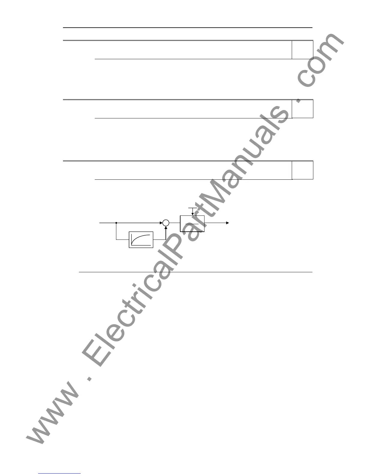
P1338[3] Resonance damping gain V/f Min: 0.00
CStat: CUT Datatype: Float Unit: - Def: 0.00
P-Group: CONTROL Active: Immediately QuickComm.: No Max: 10.00
Defines resonance damping gain for V/f. Here, di/dt of the acitve current will be scaled by P1338 (see
diagram below). If di/dt increases the resonance damping circuit decreases the inverter output frequency.
P1338
T
1338P
fi
-
active
res damping
Index:
P1338[0] : 1st. Drive data set (DDS)
P1338[1] : 2nd. Drive data set (DDS)
P1338[2] : 3rd. Drive data set (DDS)
Note:
- The resonance damping function is used to dampen oscillations in the active current. These especially
occur when rotating field motors are operating under no-load conditions. The parameter is not used to
optimize the stabilizing behavior.
- In the V/f control modes (refer to P1300), the resonance damping controller is activate in a range from
approximately 5 % up to 70 % of the rated motor frequency (P0310).
- An excessively high value results in instability (positive feedback).
Level
2
Level
3
Level
3

 Loading...


