Issue 01/06 Parameter Description
MICROMASTER 440 Parameter List
6SE6400-5BB00-0BP0
231
r2250 CO: Output setpoint of PID-MOP Min: -
Datatype: Float Unit: % Def: -
P-Group: TECH Max: -
Displays output setpoint of motor potentiometer in [%].
% 100
P2000
f
act
⋅
1
0
1
0
t
t
t
DIN
BOP
USS
CB
COM link
1
0
t
P2235
P2236
P0840
r2250
% 100
P2000
P1080
⋅
% 100
P2000
P1082
⋅
% 100
P2000
P1080
⋅−
% 100
P2000
P1082
⋅−
%
Note:
r2250 = 100 % corresponds to 4000 hex
P2251 PID mode Min: 0
CStat: CT Datatype: U16 Unit: - Def: 0
P-Group: TECH Active: Immediately QuickComm.: No Max: 1
Configuration of PID controller.
Possible Settings:
0 PID as setpoint
1 PID as trim
Common Settings:
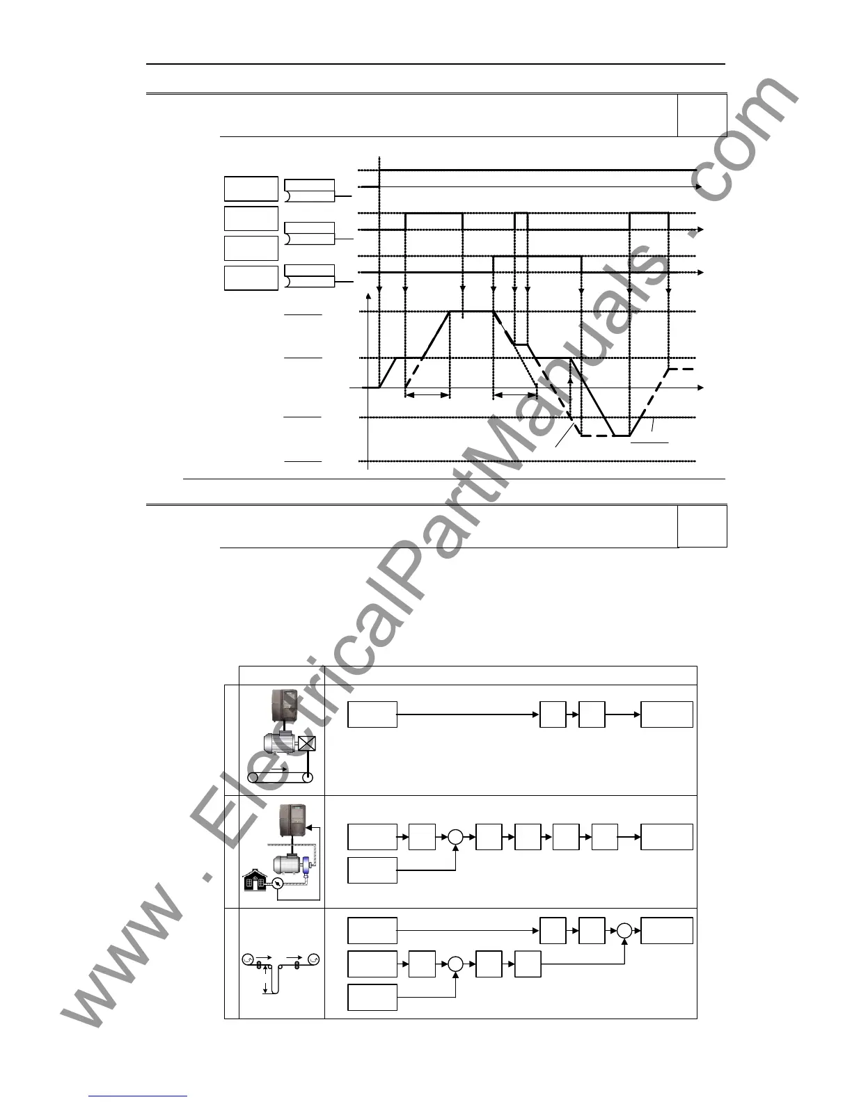
In addition to the open-loop/closed-loop control of a three-phase motor (standard applications for a drive
inverter), MICROMASTER has a technological controller that can be used to control (closed-loop) process
quantities such as pressure, filling level or control a winder. These applications and the closed-loop control
structures required to implement these are shown in the following diagram.
Application Control structure
SUM
setpoint
PID
RFG
PID
AFM RFG
x
2
v
2
v
1
4
2
PID
setpoint
PID
feedback
PID
RFG
PID
PID
limit
AFM RFG
v
2
*
x
2
*
x
2
p
2
*
p
2
−
−
PID
setpoint
PID
feedback
PID
limit
Motor
control
Motor
control
PID control
Dancer control
Variable speed drive (VSD)
1
3
p
2
SUM
setpoint
AFM RFG
Motor
control
v
Level
2
Level
3

 Loading...


