Issue 01/06 Parameter Description
MICROMASTER 440 Parameter List
6SE6400-5BB00-0BP0
151
P1253[3] Vdc-controller output limitation Min: 0.00
CStat: CUT Datatype: Float Unit: Hz Def: 10.00
P-Group: FUNC Active: Immediately QuickComm.: No Max: 600.00
Limits maximum effect of Vdc max controller.
Index:
P1253[0] : 1st. Drive data set (DDS)
P1253[1] : 2nd. Drive data set (DDS)
P1253[2] : 3rd. Drive data set (DDS)
P1254 Auto detect Vdc switch-on levels Min: 0
CStat: CT Datatype: U16 Unit: - Def: 1
P-Group: FUNC Active: Immediately QuickComm.: No Max: 1
Enables/disables auto-detection of switch-on levels for Vdc control functionalities.
Following switch-on levels are calculated
- Switch-on level chopper
- Switch-on level compound brake
- Switch-on level Vdc_max controller r1242
P1254 does not have any effect on the
- Switch-on level kin. buffering r1246
Possible Settings:
0 Disabled
1 Enabled
Note:
The switch-on thresholds are only calculated during the start-up of the inverter after connection to the
mains. An online-adaption is not performed during operation. This means that modification of P1254 does
not immediately take effect and variations in the mains are also not initially taken into account.
P1254 = 0 (Automatic Detection disabled):
The above thresholds are calculated via P0210, if automatic detection is disabled.
P1256[3] Reaction of kinetic buffering Min: 0
CStat: CT Datatype: U16 Unit: - Def: 0
P-Group: FUNC Active: Immediately QuickComm.: No Max: 2
Enters reaction for kinetic buffering controller (Vdc-min controller).
Depending on the setting selected, the frequency limit defined in P1257 is used to either hold the speed or
disable pulses. If not enough regeneration is produced, drive may trip undervoltage.
Possible Settings:
0 Maintain DC-link until trip
1 Maintain DC-link until trip / stop
2 Control stop
Index:
P1256[0] : 1st. Drive data set (DDS)
P1256[1] : 2nd. Drive data set (DDS)
P1256[2] : 3rd. Drive data set (DDS)
Note:
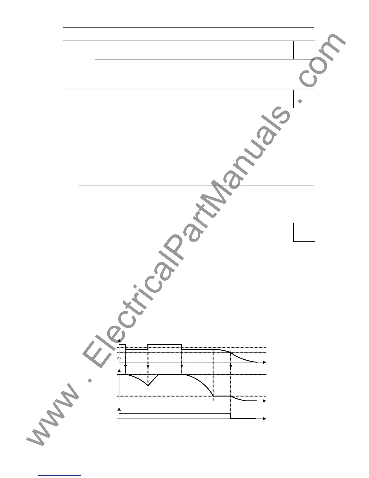
P1256 = 0:
Maintain dclink voltage until mains is returned or drive is tripped undervoltage. The frequency is kept above
the frequency limit provided in P1257.
P1245
t
0
1
V
DC
t
t
f
V
DC_min
P1257
Pulse
enabled
Level
3
Level
3
Level
3

 Loading...


