Communication processor and Modbus TCP
13.4 Universal serial interface (USS) communication
S7-1200 Programmable controller
1164 System Manual, V4.2, 09/2016, A5E02486680-AK
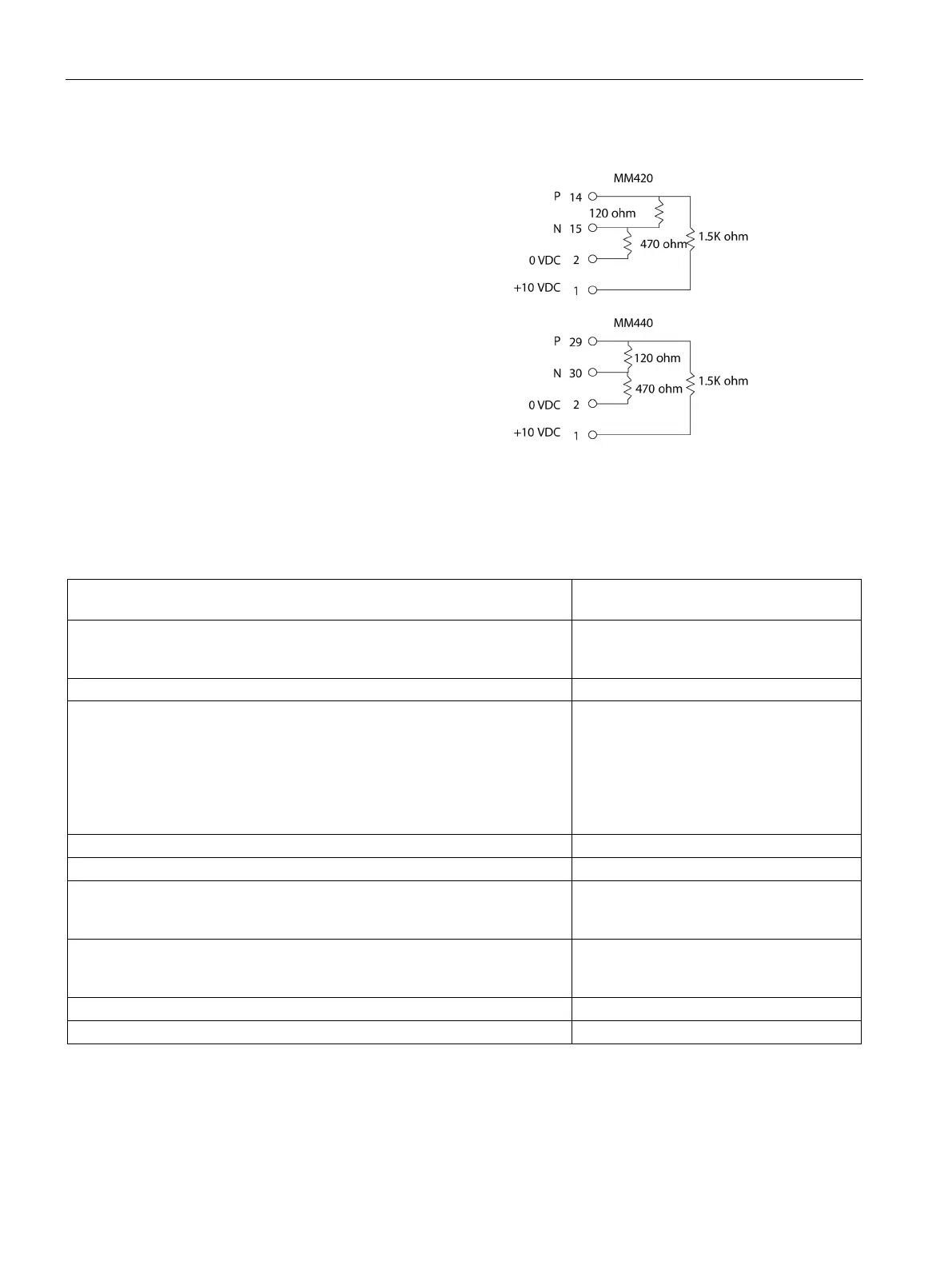
If the drive is configured as the terminating
node in the network, then termination and
bias resistors must also be wired to the
appropriate terminal connections. This
diagram shows examples of the MM4 drive
connections necessar
y for termination and
Before you connect a drive to the S7-1200, you must ensure that the drive has the following
system parameters. Use the keypad on the drive to set the parameters:
1. Reset the drive to factory settings (optional). P0010=30
If you skip step 1, then ensure that these parameters are set to the indicated
values.
USS PZD length = P2012 Index 0=(2, 4, 6,
or 8)
USS PKW length = P2013 Index 0=4
2. Enable the read/write access to all parameters (Expert mode).
3. Check the motor settings for your drive. The settings will vary according to
the motor(s) being used.
To set the parameters P304, P305, P307, P310, and P311, you must first set
parameter P010 to 1 (quick commissioning mode). When you are finished
setting the parameters, set parameter P010 to 0. Parameters P304, P305,
P307, P310, and P311 can only be changed in the quick commissioning
P0304 = Rated motor voltage (V)
P0305 = Rated motor current (A)
P0307 = Rated motor power (W)
P0310 = Rated motor frequency (Hz)
P0311 = Rated motor speed
4. Set the local/remote control mode.
5. Set selection of frequency set-point to USS on COM link.
6. Ramp up time (optional)
This is the time in seconds that it takes the motor to accelerate to maximum
P1120=(0 to 650.00)
7. Ramp down time (optional)
This the time in seconds that it takes the motor to decelerate to a complete
P1121=(0 to 650.00)
8. Set the serial link reference frequency:
9. Set the USS normalization:

 Loading...


