Technical specifications
A.12 Technology modules
S7-1200 Programmable controller
System Manual, V4.2, 09/2016, A5E02486680-AK
1491
For details about pin assignment, see table, Connector pin locations for SM 1278 I/O-Link
Master (6ES 278-4BD32-0XB0). (Page 1485)
The following table shows the terminal assignments for the SM 1278 4xIO-Link Master:
1
2
3
4
• M
n
: ground to slave
• C/Q
n
: SDLC, DI or DQ
• L
n
: 24 V DC to slave
• M: ground
• L+: 24 V DC to Master
• RES: reserved; may not
be assigned
A1
1
2
3
4
1
2
3
4
4 RES RES RES RES
3
RES RES RES
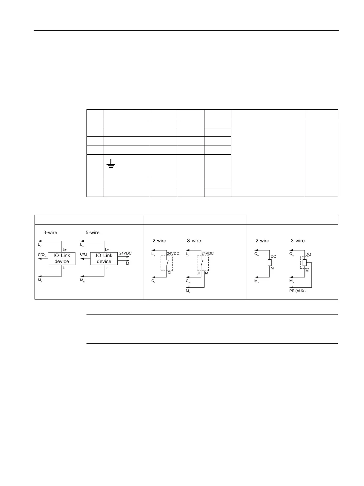
The following table contains illustrations of connection examples, where n = port number:
Note
Connected sensors must use the device supply provided by the Master module L
n

 Loading...


