Basic instructions
8.1 Bit logic operations
S7-1200 Programmable controller
230 System Manual, V4.2, 09/2016, A5E02486680-AK
Table 8- 7 Data types for the parameters
● If there is power flow through an output coil or an FBD "=" box is enabled, then the output
bit is set to 1.
● If there is no power flow through an output coil or an FBD "=" assignment box is not
enabled, then the output bit is set to 0.
● If there is power flow through an inverted output coil or an FBD "/=" box is enabled, then
the output bit is set to 0.
● If there is no power flow through an inverted output coil or an FBD "/=" box is not enabled,
then the output bit is set to 1.
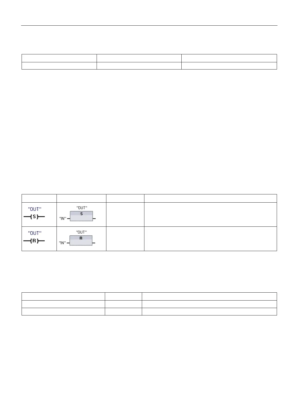
Set and reset instructions
Set and Reset 1 bit
Table 8- 8 S and R instructions
Not available Set output:
When S (Set) is activated, then the data value at the OUT
address is set to 1. When S is not activated, OUT is not
changed.
Not available Reset output:
When R (Reset) is activated, then the data value at the OUT
address is set to 0. When R is not activated, OUT is not
For LAD and FBD: These instructions can be placed anywhere in the network.
2
For SCL: You must write code to replicate this function within your application.
Table 8- 9 Data types for the parameters
IN (or connect to contact/gate logic)
Bit tag of location to be monitored
Bit tag of location to be set or reset

 Loading...


