Installation
4.3 Installation and removal procedures
S7-1200 Programmable controller
System Manual, V4.2, 09/2016, A5E02486680-AK
69
Installing and removing the expansion cable
The S7-1200 expansion cable provides additional flexibility in configuring the layout of your
S7-1200 system. Only one expansion cable is allowed per CPU system. You install the
expansion cable either between the CPU and the first SM, or between any two SMs.
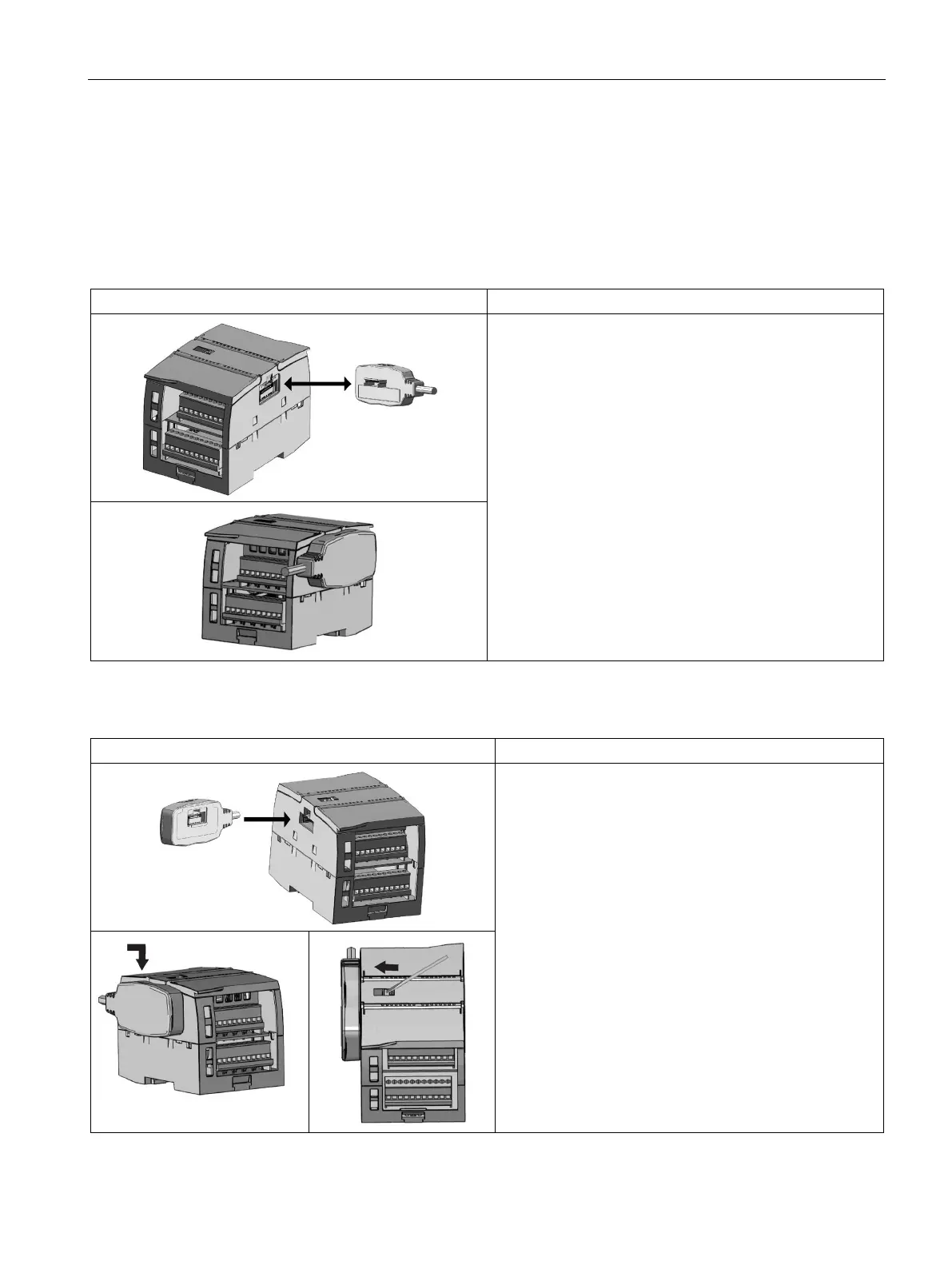
Table 4- 12 Installing and removing the male connector of the expansion cable
To install the male connector:
1. Ensure that the CPU and all S7-1200 equipment are
disconnected from electrical power.
2. Push the connector into the bus connector on the right
side of the signal module or CPU.
To remove the male connector:
1. Ensure that the CPU and all S7-1200 equipment are
disconnected from electrical power.
2. Pull out the male connector to release it from the signal
module or CPU.
Table 4- 13 Installing the female connector of the expansion cable
1. Ensure that the CPU and all S7-1200 equipment are
disconnected from electrical power.
2.
Place the female connector to the bus connector on the
left side of the signal module.
3.
Slip the hook extension of the female connector into the
housing at the bus connector and press down slightly
to engage the hook.
4. Lock the connector into place:
– Place a screwdriver beside the tab on the top of the
signal module.
– Slide the tab fully to the left.
To engage the connector, you must slide the connector tab
all the way to the left. The connector tab must be locked
into place.

 Loading...


