Technical specifications
A.6 CPU 1214C
S7-1200 Programmable controller
System Manual, V4.2, 09/2016, A5E02486680-AK
1405
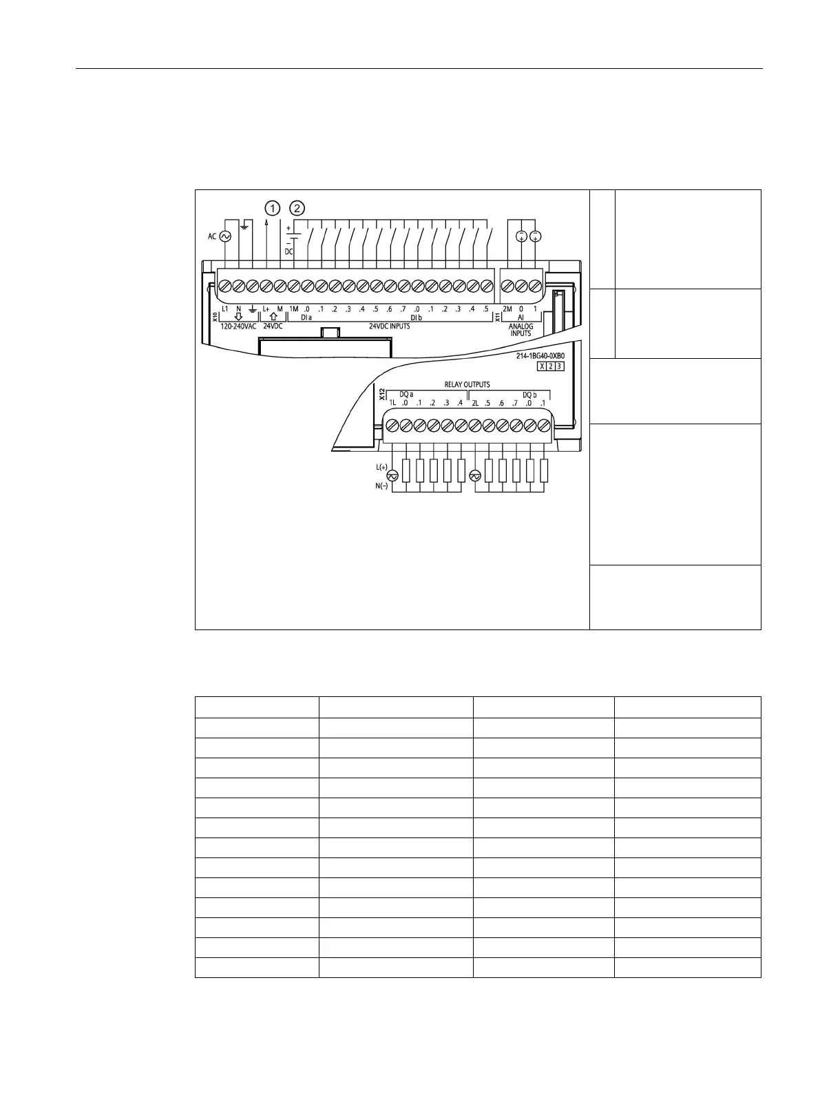
CPU 1214C wiring diagrams
Table A- 60 CPU 1214C AC/DC/Relay (6ES7214-1BG40-0XB0)
24 V DC Sensor Power
Out
For additional noise
chassis ground even if
②
For sinking inputs, con-
nect "-" to "M" (shown).
For sourcing inputs,
Note 1: X11 connectors must
be gold. See Appendix C,
Spare Parts for article num-
Note 2: Either the L1 or N
(L2) terminal can be con-
nected to a voltage source
up to 240 V AC. The N ter-
minal can be considered L2
and is not required to be
grounded. No polarization is
required for L1 and N (L2)
terminals.
Note 3: See Device Configu-
ratio (Page 153)n for infor-
mation about the Ethernet
Table A- 61 Connector pin locations for CPU 1214C AC/DC/Relay (6ES7214-1BG40-0XB0)

 Loading...


